Design and analysis of stress-free clamping of mirrors used in free-electron laser beamlines
-
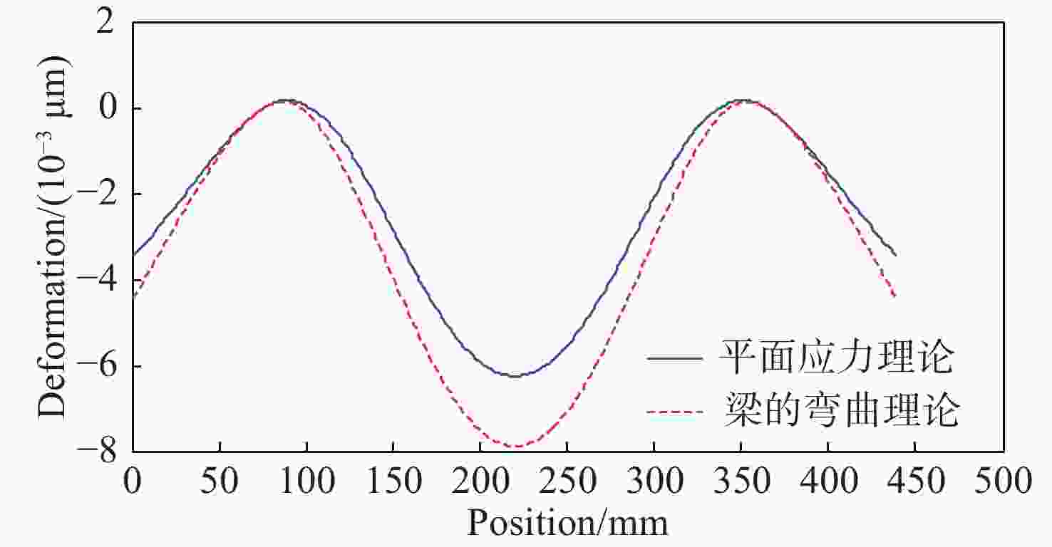
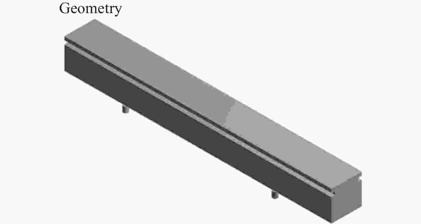
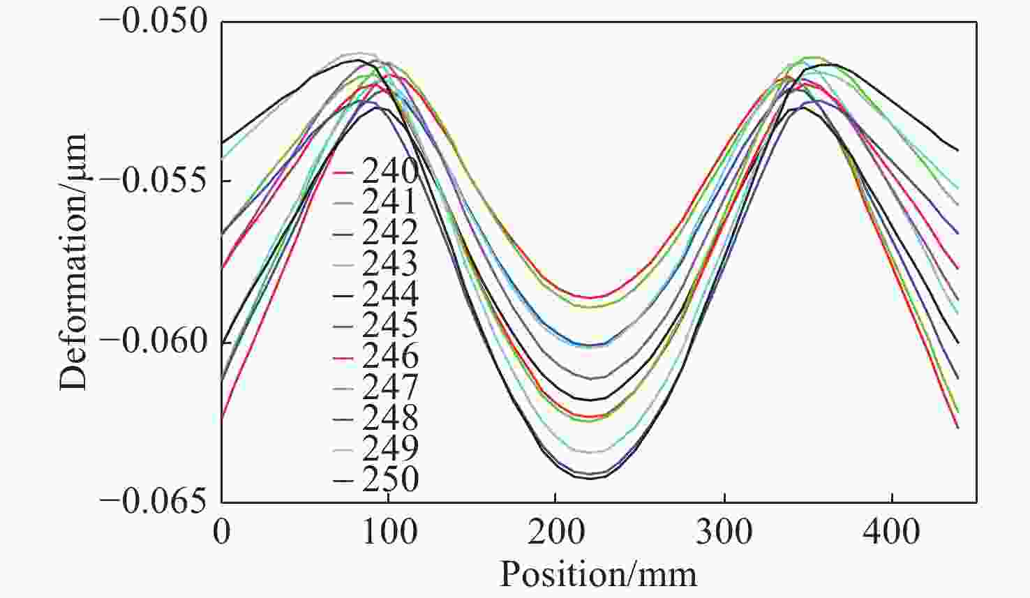
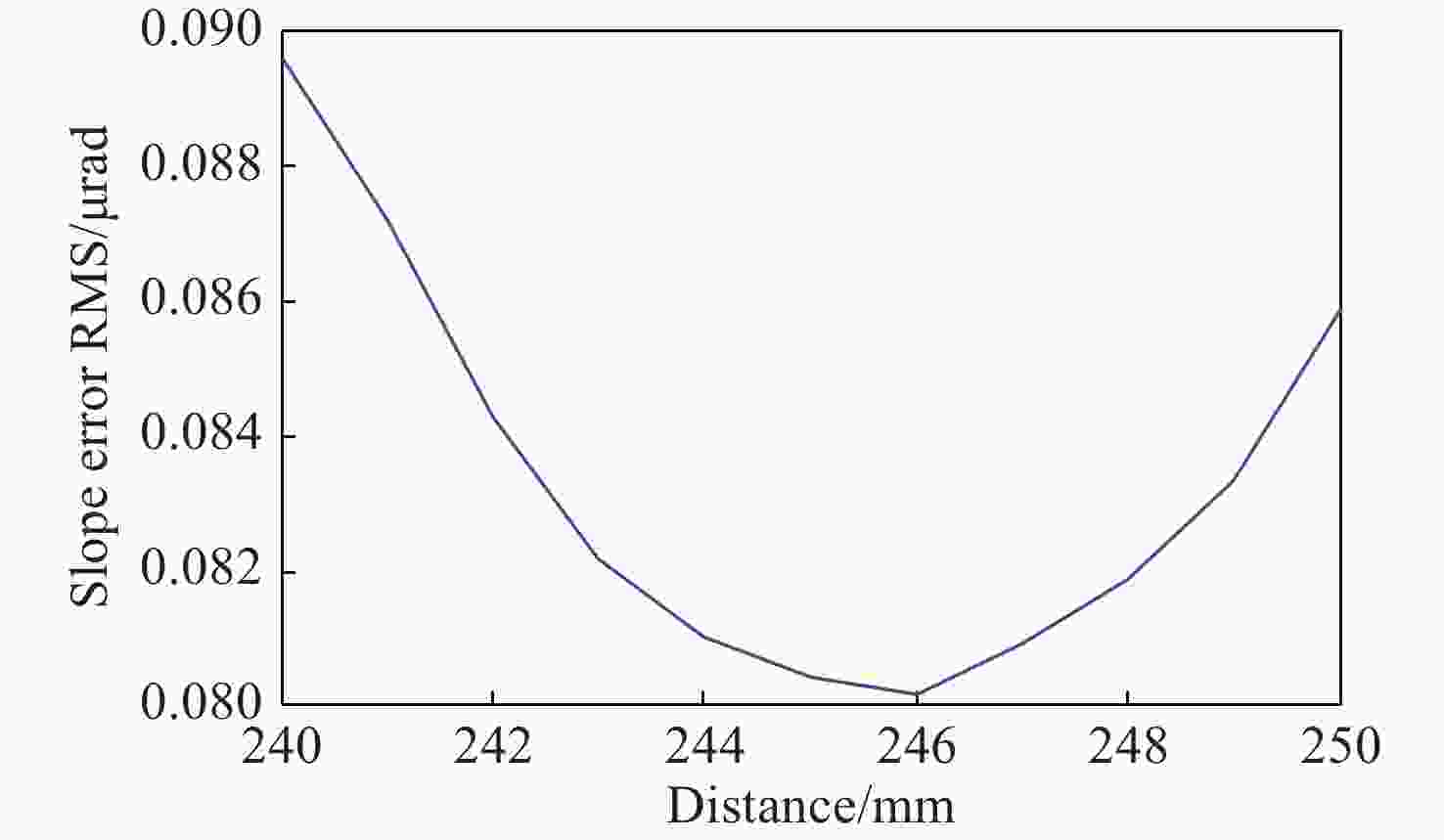
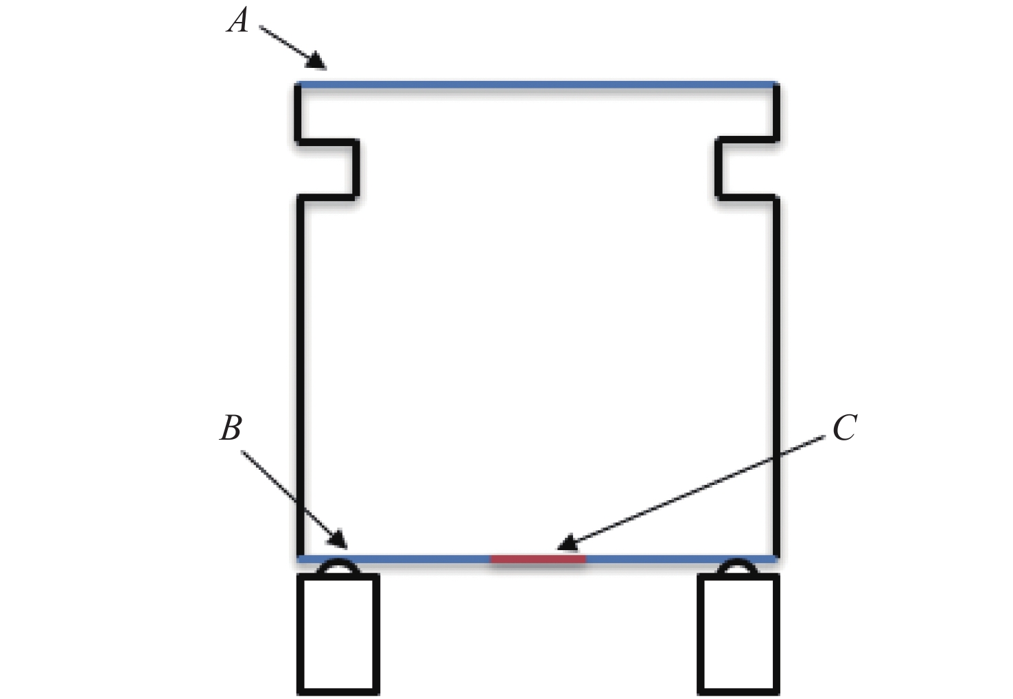
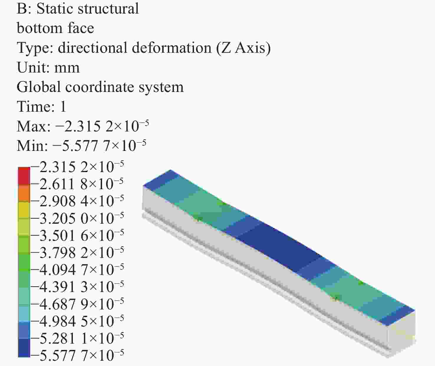
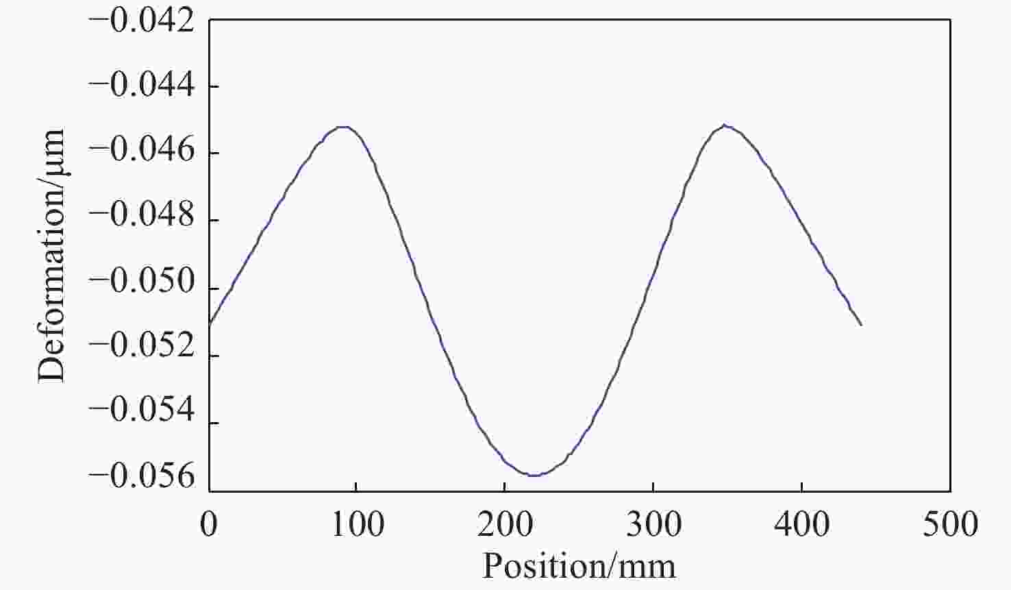
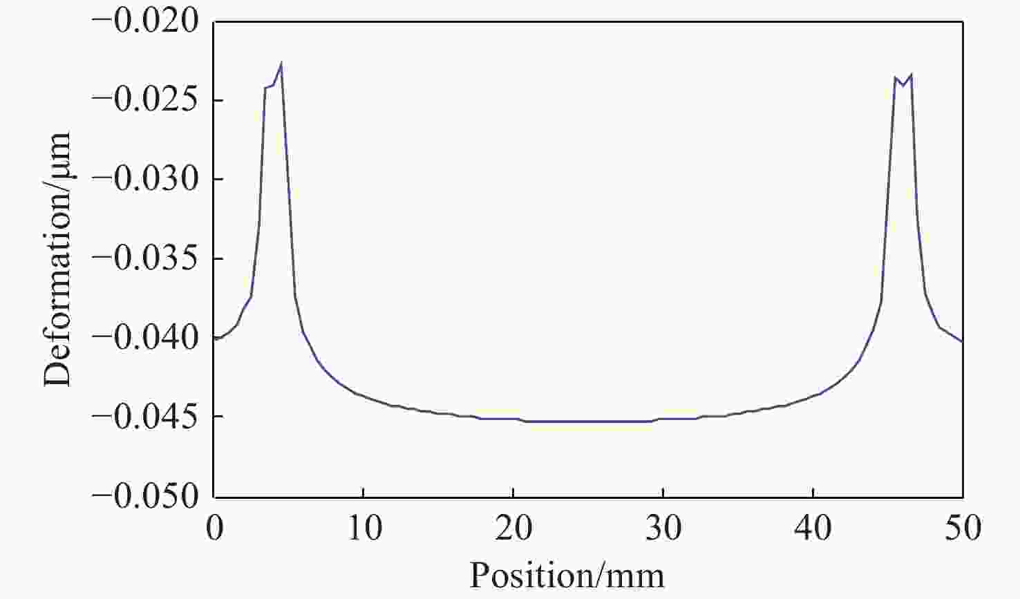
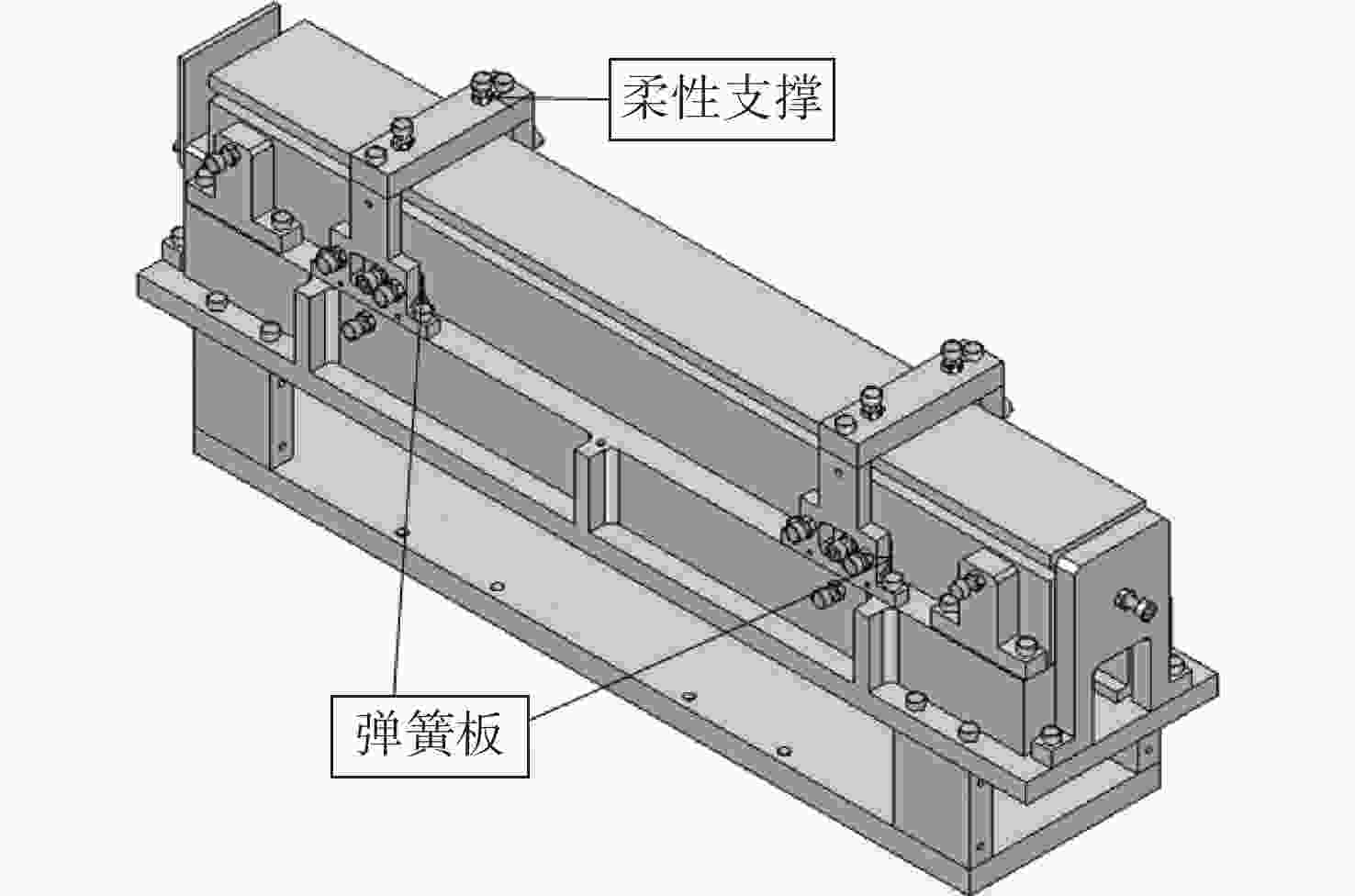
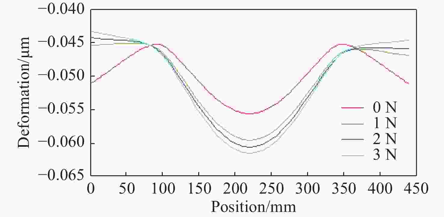
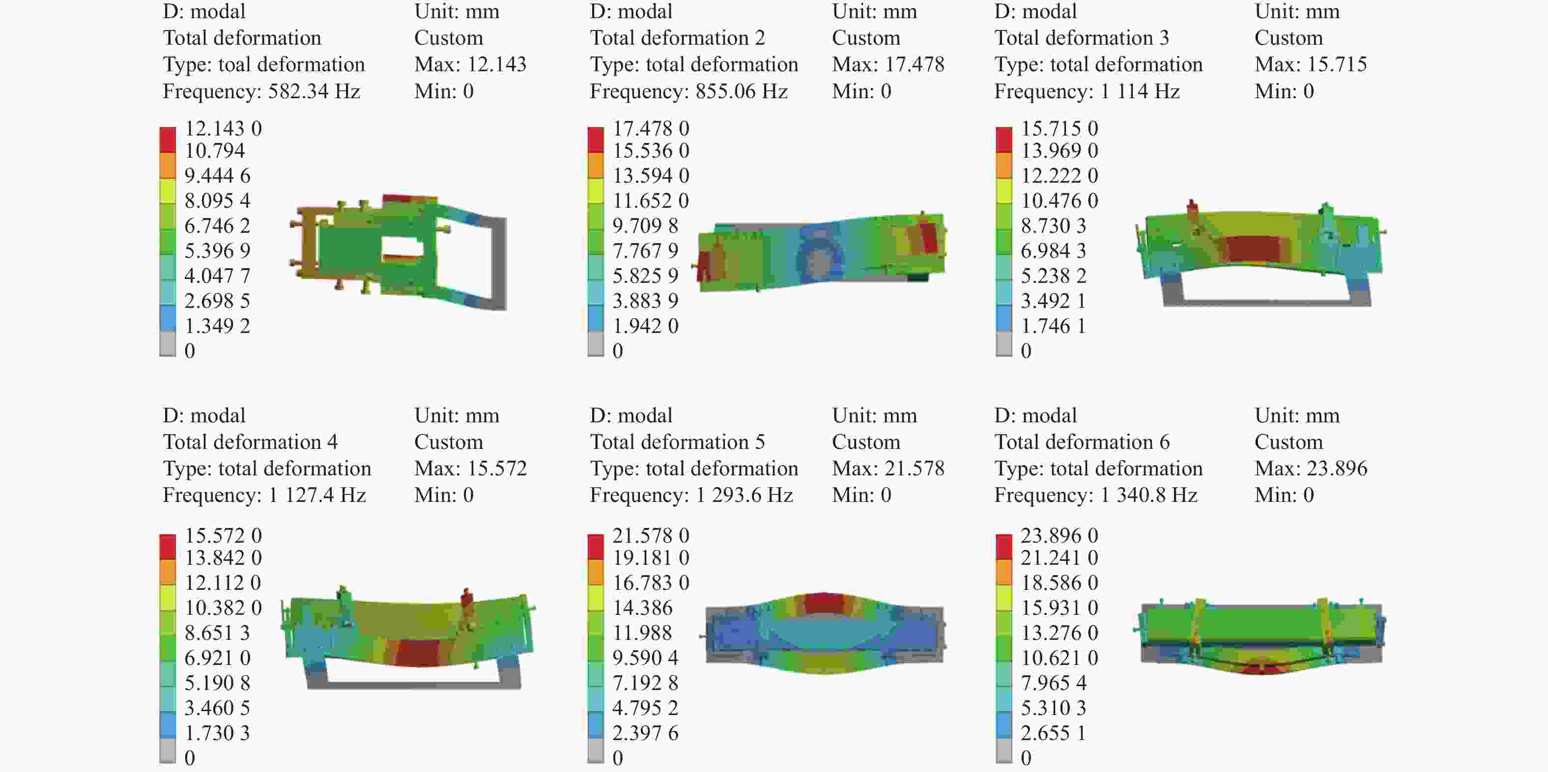
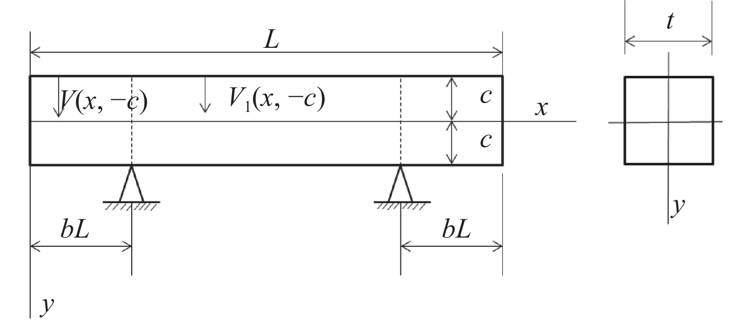
摘要: 反射镜是自由电子激光光束线中的重要光学元件,反射镜自重引起的面形误差会严重影响光束线的成像质量。为减小自重引起的面形误差,基于Bessel点理论提出了重力补偿方案,并设计了无应力夹持装置,利用有限元软件对该装置进行仿真分析。以尺寸为440 mm×50 mm×50 mm的反射镜为例进行分析,传统支撑方式下反射镜下表面面形误差为1.647 μrad,采用本文提出的夹持方案后面形误差降至0.085 7 μrad,优于工程指标0.1 μrad。为防止反射镜在工作模式切换时发生窜动,可对反射镜添加不超过2 N的微小夹持力,此时反射镜的面形误差为0.093 9 μrad。此外,还对装置进行了动力学分析,结果显示:该设计方案可有效防止装置存在较低的固有频率,在使用过程中不会产生共振现象,满足光束线的使用需求。Abstract: The reflector is an important optical element in free-electron laser beamlines. Deformation error caused by gravity can seriously affect the image quality of a beamline. To reduce deformation error, a gravity compensation scheme based on the Bessel point theory is proposed and a stress-free clamping device is designed. Taking a 440 mm × 50 mm × 50 mm mirror as an example, the analysis results indicate that the deformation error in the bottom surface of a mirror clamped with the traditional support method is 1.647 μrad. Adopting the newly designed device proposed in this paper, the results of a finite element analysis showed that the deformation error reduced to 0.085 7 μrad, which is better than the engineering index of 0.1 μrad. To prevent the mirror from moving when switching modes, a small clamping force of no more than 2 N can be added to the mirror, at which point the surface error of the mirror becomes 0.093 9 μrad. Additionally, a dynamic analysis of the device is also carried out, which indicates that the device mutes the low natural frequency, which means that resonance will not occur during operation. Therefore, this scheme satisfies our requirements for the beamline.
-
表 1 反射镜主要参数
Table 1. The main parameters of mirror
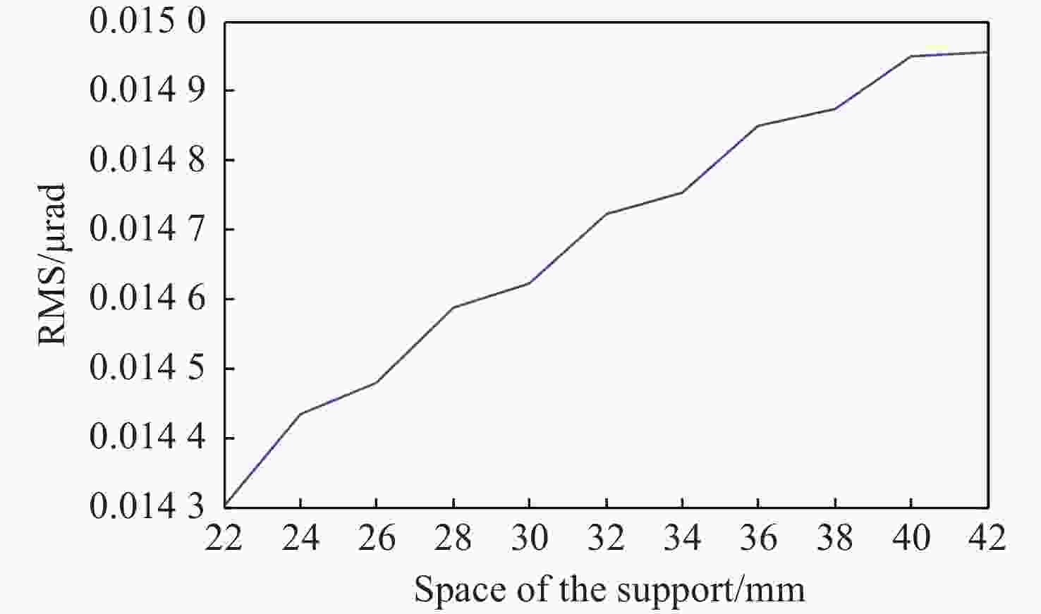
Substrate material Single-crystalline Si Coating B4C Mirror dimension/mm 440x50x50 Footprint on mirror/mm 380x10 Useful area/mm 400x30 Incidence angle/(°) 1.5 Mirror radius ∞/>30 km Slope error/μrad 0.1 Roughness/nm 0.3 表 2 弧矢方向支撑间距为22, 28, 36和42 mm时支撑点处不同线段的面形误差RMS
Table 2. Deformation error RMS of different lines at support point when the space of the support along sagittal are 22, 28, 36, 42 mm (μrad)
RMS 22 mm 28 mm 36 mm 42 mm A 0.014 3 0.014 59 0.014 85 0.014 96 B 2.893 2.885 2.866 9 3.19 C 0.116 8 0.059 8 0.032 0.016 7 -
[1] 赵振堂, 冯超. X射线自由电子激光[J]. 物理,2018,47(8):481-490. doi: 10.7693/wl20180801ZHAO ZH T, FENG CH. X-ray free electron lasers[J]. Physics, 2018, 47(8): 481-490. (in Chinese) doi: 10.7693/wl20180801 [2] ASSOUFID L, HIGNETTE O, HOWELLS M, et al. Future metrology needs for synchrotron radiation grazing-incidence optics[J]. Nuclear Instruments and Methods in Physics Research Section A:Accelerators,Spectrometers,Detectors and Associated Equipment, 2001, 467-468: 267-270. [3] 卢启鹏, 高飒飒, 彭忠琦. 同步辐射水平偏转压弯镜面形误差分析与补偿[J]. 光学精密工程,2011,19(11):2644-2650. doi: 10.3788/OPE.20111911.2644LU Q P, GAO S S, PENG ZH Q. Analysis and compensation of slope error for synchrotron radiation horizontal deflected mirror[J]. Optics and Precision Engineering, 2011, 19(11): 2644-2650. (in Chinese) doi: 10.3788/OPE.20111911.2644 [4] 孙福权, 傅远, 祝万钱, 等. 压弯镜系统自重平衡多点调节方法的研究[J]. 核技术,2011,34(4):246-250.SUN F Q, FU Y, ZHU W Q, et al. A study on multi-point gravity compensation of mirror bending system[J]. Nuclear Techniques, 2011, 34(4): 246-250. (in Chinese) [5] MORI Y, YAMAMURA K, SANO Y. The study of fabrication of the x-ray mirror by numerically controlled plasma chemical vaporization machining: development of the machine for the x-ray mirror fabrication[J]. Review of Scientific Instruments, 2000, 71(12): 4620. doi: 10.1063/1.1322580 [6] SENBA Y, KISHIMOTO H, MIURA T, et al. Upgrade of surface profiler for x-ray mirror at SPring-8[J]. Proceedings of SPIE,SPIE, 2014, 9206: 920604. [7] 黄智超, 程建高, 李飞, 等. 同步辐射压弯镜重力补偿方法[J]. 强激光与粒子束,2018,30(8):085102. doi: 10.11884/HPLPB201830.180066HUANG ZH CH, CHENG J G, LI F, et al. Gravity compensation for bent mirror of synchrotron radiation[J]. High Power Laser and Particle Beams, 2018, 30(8): 085102. (in Chinese) doi: 10.11884/HPLPB201830.180066 [8] 李庆祥, 王东生, 李玉和. 现代精密仪器设计[M]. 北京: 清华大学出版社, 2004: 64-65.LI Q X, WANG D SH, LI Y H. Design of Modern Precision Instruments[M]. Beijing: Tsinghua University Press, 2004: 64-65. (in Chinese) [9] REED R R. A glass beam reference surface for quality control measurements[J]. International Journal of Mechanical Sciences, 1966, 8(11): 703-715. doi: 10.1016/0020-7403(66)90049-X [10] 邵明振, 邵春雷, 卢启鹏, 等. 高功率TEA CO2激光器主机结构优化设计[J]. 发光学报,2013,34(3):388-393. doi: 10.3788/fgxb20133403.0388SHAO M ZH, SHAO CH L, LU Q P, et al. Design on mainframe of high power TEA CO2 laser and optimization[J]. Chinese Journal of Luminescence, 2013, 34(3): 388-393. (in Chinese) doi: 10.3788/fgxb20133403.0388 [11] 程显超. 同步辐射束线工程中相关技术的研究[D]. 合肥: 中国科学技术大学, 2016.CHENG X CH. Research on the beamline engineering technologies for the synchrotron radiation[D]. Hefei: University of Science and Technology of China, 2016. (in Chinese) [12] 翟岩, 梅贵, 江帆, 等. Ф2020 mm口径空间红外相机主反射镜设计[J]. 发光学报,2018,39(8):1170-1176. doi: 10.3788/fgxb20183908.1170ZHAI Y, MEI G, JIANG F, et al. Ф2020 mm aperture space infrared camera main reflector design[J]. Chinese Journal of Luminescence, 2018, 39(8): 1170-1176. (in Chinese) doi: 10.3788/fgxb20183908.1170 [13] NIJSSE G J P. Linear motion systems: a modular approach for improved straightness performance[D]. Delft: Delft University of Technology, 2001: 39-40. -


 下载:
下载:
