


Compact voice coil deformable mirror with high wavefront fitting precision
doi: 10.37188/CO.EN-2023-0001
-
摘要:
为了满足小型化自适应光学系统校正波前畸变的需求,基于系统理论分析设计了一种使用微型音圈驱动器的变形镜。使用电磁理论和有限元方法优化了微型音圈驱动器的结构参数。从热变形、共振频率、耦合系数等多个参数的角度对变形镜进行了优化。最后根据影响函数完成了波前拟合和残差计算。优化后的69单元紧凑型音圈变形镜具有大相位调制量、良好的热稳定性,第一共振频率为2220 Hz。对于PV值为1 µm的前35项泽尼克模式,紧凑型音圈变形镜的拟合残差均小于30 nm。对于复杂随机像差,紧凑型VCDM能够将波前RMS降至原来的10%以下。结果表明,与传统的音圈变形镜相比,紧凑型音圈变形镜具有更高的波前拟合精度。高性能、低成本的紧凑型音圈变形镜在视网膜成像和机载成像系统中具有良好的应用前景。
Abstract:To meet the requirements of wavefront distortion correction for miniaturized adaptive optics systems, a Deformable Mirror (DM) using micro voice coil actuators was designed based on systematic theoretical analysis. The structural parameters of the micro voice coil actuator were optimized by electromagnetic theory and the finite element method. The DM was optimized with respect to thermal deformation, resonance frequency, coupling coefficient and other parameters. Finally, wavefront fitting and residual calculation were completed according to the influence function. The optimized 69-element Voice Coil Deformable Mirror (VCDM) has a large phase stroke, good thermal stability, and a large first resonance of 2220 Hz. The RMS of the fitting residuals of the VCDM for the first 35 Zernike modes with a PV value of 1 μm are all below 30 nm. For complex random aberrations, the compact VCDM can reduce the wavefront RMS to less than 10%. Compared with a traditional VCDMs, the results of our compact VCDM indicate that it has a higher wavefront fitting precision. The compact VCDM with high performance and low cost has good potential applications in human retinal or airborne imaging systems.
-
Key words:
- adaptive optics /
- deformable mirror /
- voice coil actuator /
- multiparameter analysis
-

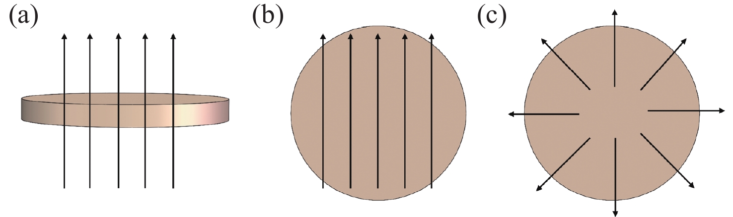
Figure 3. Magnetization directions of the permanent magnet. (a) Axial magnetization, (b) parallel magnetization, (c) radial magnetization

Figure 4. Electromagnetic force as a function of current for the permanent magnet at different magnetization directions

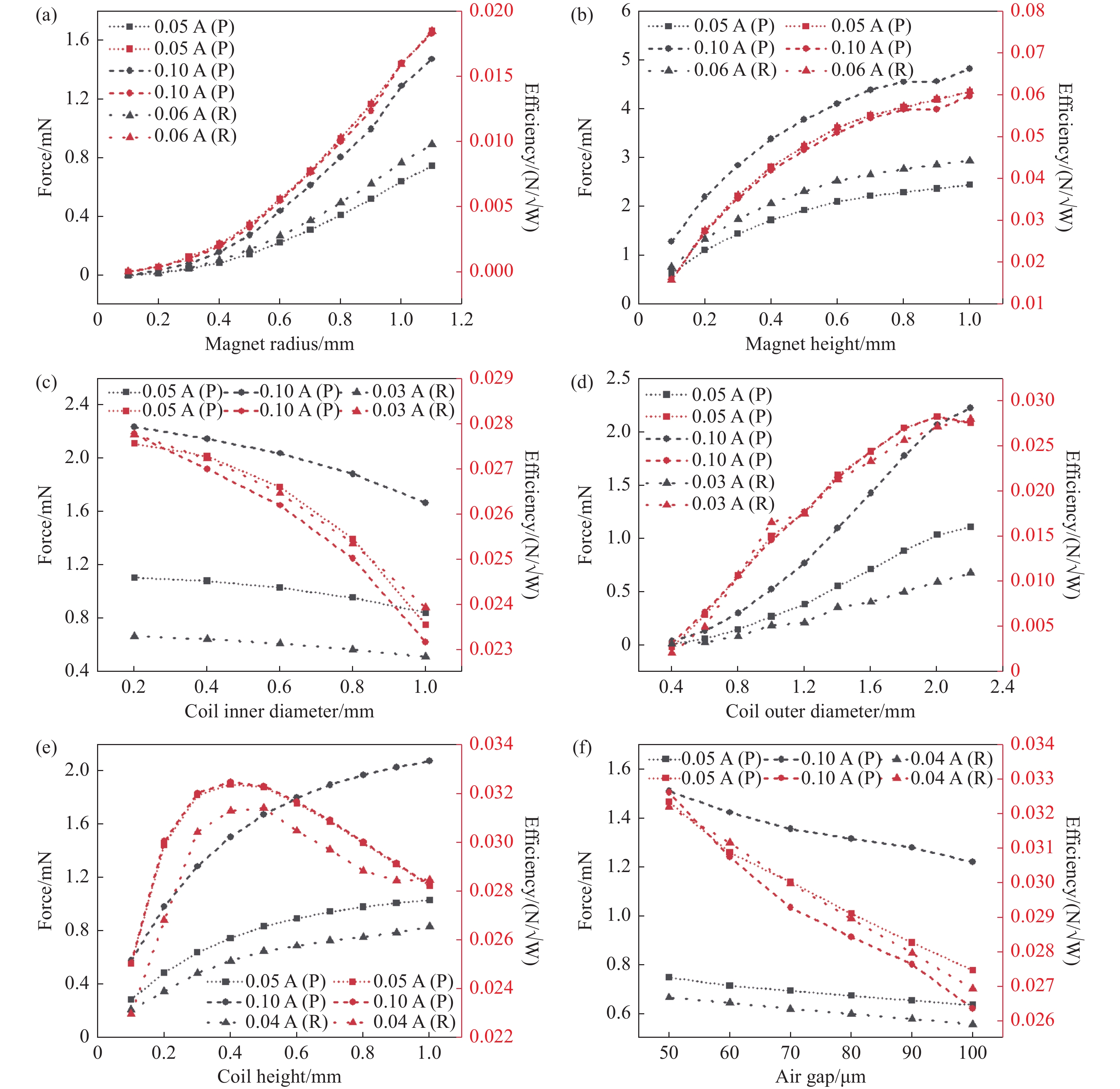
Figure 5. Force and efficiency as a function of the VCA’s structural parameters: (a) permanent magnet radius; (b) permanent magnet height; (c) coil inner diameter; (d) coil outer diameter; (e) coil height; (f) air gap

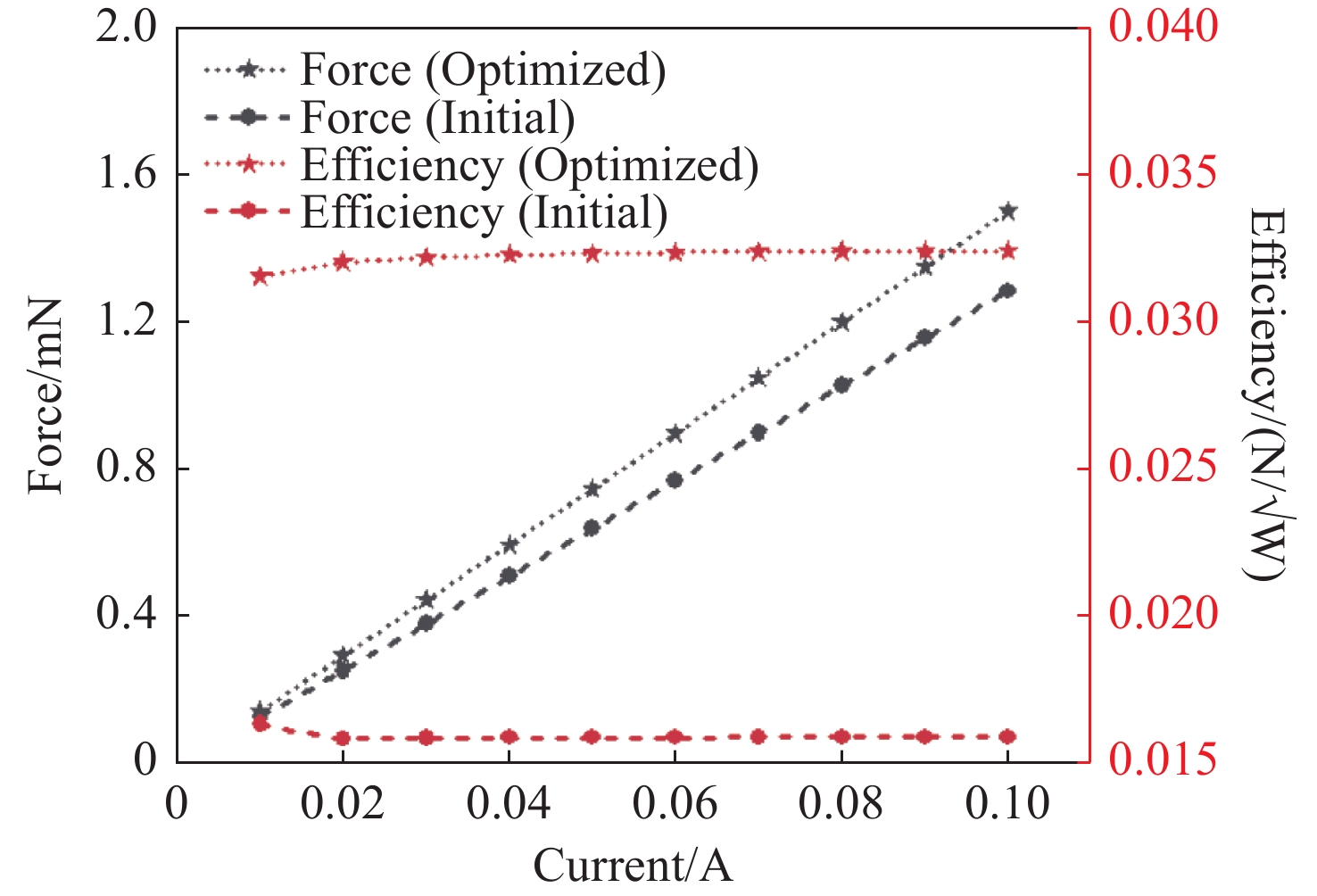
Figure 6. Electromagnetic force and efficiency as a function of current (Circle line, before optimization; pentagram line, after optimization)

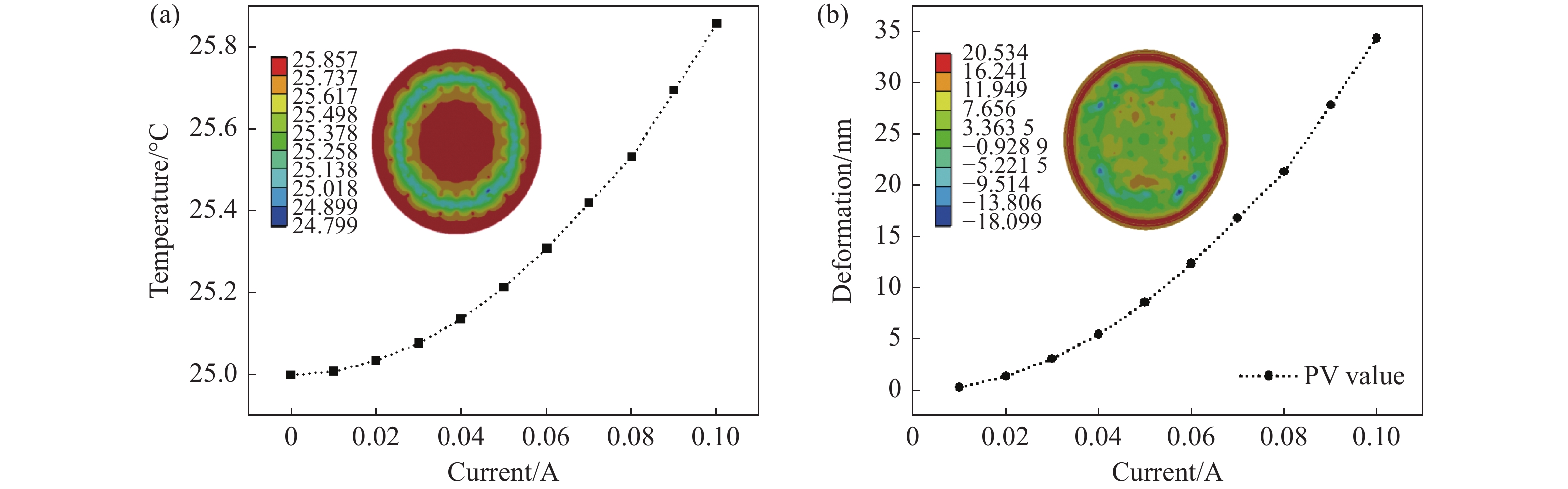
Figure 8. Temperature and thermal deformation of the VCDM’s thin mirror as a function of current. (a) The temperature of the thin mirror as a function of current. The inset shows the temperature chart of the thin mirror when the current is 0.1 A. (b) The thermal deformation chart of the mirror surface as a function of current. The inset shows the deformation chart of the thin mirror when the current is 0.06 A

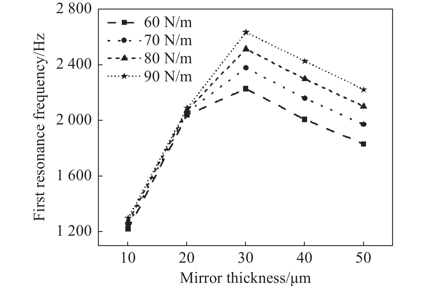
Figure 9. Relationship between first resonance frequency of the DM and mirror thickness under different spring's stiffnesses

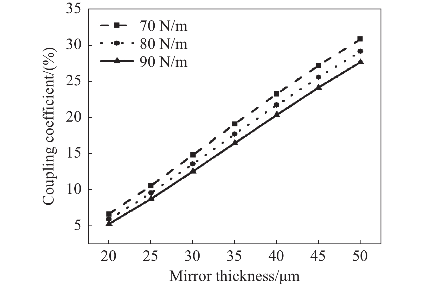
Figure 10. Relationship between coupling coefficient of the DM and mirror thickness under different spring's stiffnesses

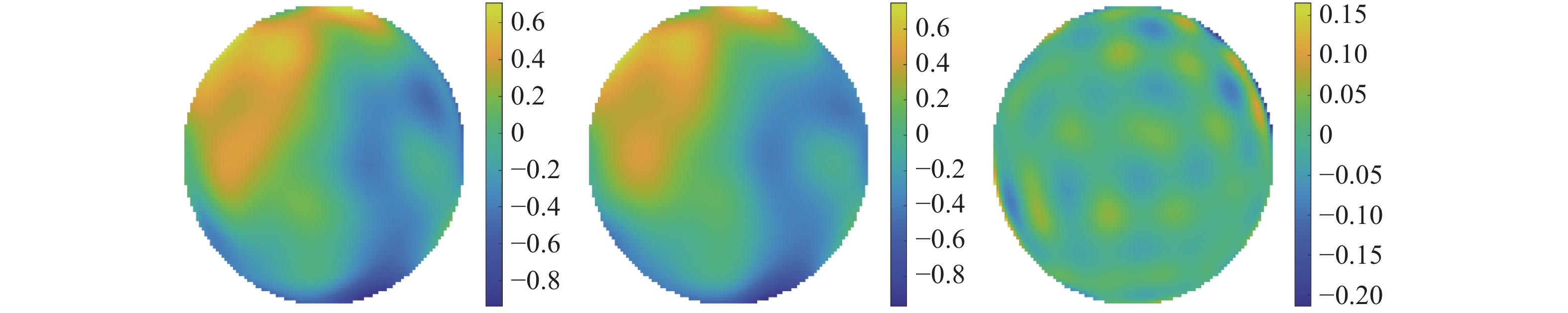
Figure 14. The wavefront fitting results of S1 for complex random aberrations. From left to right, there is the original wavefront, the fitting wavefront and the residual wavefront
Table 1. Parameters for micro VCAs to be optimized
Parameters Values(mm) Step Magnet radius rm 0.1≤rm≤1.1 0.1 Magnet height hm 0.05≤hm≤1 0.05 Coil inner diameter dc-in 0.2≤dc-in≤1 0.2 Coil outer diameter dc-out 0.4≤dc-out≤2.2 0.2 Coil height hc 0.1≤hc≤1 0.1 Air gap hg 50≤hg≤100 10  下载: 导出CSV
Table 2. Material parameters uesd in thermal analysis
Material Thermal conductivity Coefficient of thermal expansion Density Young’s Modulus Poisson’s Ratio [W/m/ °C] [/ °C] [kg/m³] [Pa] [/] CP1 Polyimide 0.25 5.1×10⁻⁵ 1540 2.1×10⁹ 0.34 316 Stainless Steel 13.44 1.478×10⁻⁵ 7954 1.95×10¹¹ 0.25 Epoxy 0.294 1.688×10⁻⁵ 1900 2.64×10¹⁰ 0.1543 NdFe35 7.7 3.2×10⁻⁶ 7450 1.6×10⁸ 0.24 Copper 112.1 1.999×10⁻⁵ 8267 9.995×10¹⁰ 0.345 Aluminum Alloy 114 2.3×10⁻⁵ 2770 7.1×10¹⁰ 0.33
下载: 导出CSV
-
[1] HU L F, LIU CH, SHEN W, et al. Advancement of adaptive optics in astronomical observation[J]. Scientia Sinica Physica, Mechanica & Astronomica, 2017, 47(8): 084202. (in Chinese). [2] YUAN D B, XU L, ZHANG W B, et al. Development of a 36-element piezoelectric deformable mirror for synchrotron radiation and its surface control ability[J]. Chinese Optics, 2021, 14(6): 1362-1367. (in Chinese). doi: 10.37188/CO.2021-0103 [3] WU ZH ZH, ZHANG T Y, MBEMBA D, et al. Wavefront sensorless aberration correction with magnetic fluid deformable mirror for laser focus control in optical tweezer system[J]. IEEE Transactions on Magnetics, 2021, 57(1): 1-6. [4] KAMEL A, KOCER S, MUKHANGALIYEVA L, et al. Resonant adaptive MEMS mirror[J]. Actuators, 2022, 11(8): 224. doi: 10.3390/act11080224 [5] LIU X Y, CAO SH, HU D T, et al. Design of voice-coil deformable mirror and its mechanical characteristics[J]. Chinese Journal of Liquid Crystals and Displays, 2020, 35(8): 801-807. (in Chinese). doi: 10.37188/YJYXS20203508.0801 [6] ANDERSEN T, GARPINGER O, OWNER-PETESEN M, et al. Novel concept for large deformable mirrors[J]. Optical Engineering, 2006, 45(7): 073001. doi: 10.1117/1.2227014 [7] BRUSA G, RICCARDI A, SALINARI P, et al. MMT adaptive secondary: performance evaluation and field testing[J]. Proceedings of SPIE, 2003, 4839: 691-702. doi: 10.1117/12.459786 [8] BRIGUGLIO R, QUIRÓS-PACHECO F, MALES J R, et al. Optical calibration and performance of the adaptive secondary mirror at the Magellan telescope[J]. Scientific Reports, 2018, 8(1): 10835. doi: 10.1038/s41598-018-29171-6 [9] WRIGHT T, SPARKS H, PATERSON C, et al. Video-rate remote refocusing through continuous oscillation of a membrane deformable mirror[J]. Journal of Physics:Photonics, 2021, 3(4): 045004. doi: 10.1088/2515-7647/ac29a2 [10] MORGAN R E, DOUGLAS E S, ALLAN G W, et al. MEMS deformable mirrors for space-based high-contrast imaging[J]. Micromachines, 2019, 10(6): 366. doi: 10.3390/mi10060366 [11] FERNANDEZ E J, VABRE L, HERMANN B, et al. Adaptive optics with a magnetic deformable mirror: applications in the human eye[J]. Optics Express, 2006, 14(20): 8900-8917. doi: 10.1364/OE.14.008900 [12] ZAMKOTSIAN F, LIOTARD A, LANZONI P, et al. Electrostatic micro-deformable mirror for adaptive optics[J]. Proceedings of SPIE, 2006, 6272: 627222. doi: 10.1117/12.671632 [13] LIU L, GUO J, ZHAO SH, et al. Application of stochastic parallel gradient descent algorithm in laser beam shaping[J]. Chinese Optics, 2014, 7(2): 260-266. (in Chinese). [14] NOLL R J. Zernike polynomials and atmospheric turbulence[J]. Journal of the Optical Society of America, 1976, 66(3): 207-211. doi: 10.1364/JOSA.66.000207 [15] HARDY J W, THOMPSON L. Adaptive optics for astronomical telescopes[J]. Physics Today, 2000, 53(4): 69. [16] HAMELINCK R F M M. Adaptive deformable mirror: based on electromagnetic actuators[D]. Eindhoven: Technische Universiteit Eindhoven, 2010: 23-25. [17] DOBLE N, MILLER D T, YOON G, et al. Requirements for discrete actuator and segmented wavefront correctors for aberration compensation in two large populations of human eyes[J]. Applied Optics, 2007, 46(20): 4501-4514. doi: 10.1364/AO.46.004501 [18] ZHAO J L, XIAO F, KANG J, et al. Statistical analysis of ocular monochromatic aberrations in Chinese population for adaptive optics ophthalmoscope design[J]. Journal of Innovative Optical Health Sciences, 2017, 10(1): 1650038. doi: 10.1142/S1793545816500383 [19] JAROSZ J, MECÊ P, CONAN J M, et al. High temporal resolution aberrometry in a 50-eye population and implications for adaptive optics error budget[J]. Biomedical Optics Express, 2017, 8(4): 2088-2105. doi: 10.1364/BOE.8.002088 [20] WANG CH CH, LU SH ZH, ZHANG C Y, et al. Design and dynamic modeling of a 3-RPS compliant parallel robot driven by voice coil actuators[J]. Micromachines, 2021, 12(12): 1442. doi: 10.3390/mi12121442 [21] ZHANG ZH G, HU Q L, MA W CH, et al. Design and performance research of high efficiency variable reluctance voice coil actuator[J]. Chinese Journal of Liquid Crystals and Displays, 2022, 37(1): 21-28. (in Chinese). doi: 10.37188/CJLCD.2021-0272 [22] CUGAT O, BASROUR S, DIVOUX C, et al. Deformable magnetic mirror for adaptive optics: technological aspects[J]. Sensors and Actuators A:Physical, 2001, 89(1-2): 1-9. doi: 10.1016/S0924-4247(00)00550-1 [23] BANERJEE K, RAJAEIPOUR P, ZAPPE H, et al. A 37-actuator polyimide deformable mirror with electrostatic actuation for adaptive optics microscopy[J]. Journal of Micromechanics and Microengineering, 2019, 29(8): 085005. doi: 10.1088/1361-6439/ab2370 [24] YU E, JOSHI Y K. Natural convection air cooling of electronic components in partially open compact horizontal enclosures[J]. IEEE Transactions on Components and Packaging Technologies, 2000, 23(1): 14-22. doi: 10.1109/6144.833037 [25] HUANG L H, RAO CH H, JIANG W H. Modified Gaussian influence function of deformable mirror actuators[J]. Optics Express, 2008, 16(1): 108-114. doi: 10.1364/OE.16.000108 [26] AHN K, KIHM H. Moment actuator for correcting low-order aberrations of deformable mirrors[J]. Optics and Lasers in Engineering, 2020, 126: 105864. doi: 10.1016/j.optlaseng.2019.105864 [27] 张志高. 模块化音圈变形镜的结构设计与性能研究[D]. 无锡: 江南大学, 2022.ZHANG ZH G. Structure design and performance research of modular voice coil deformable mirror[D]. Wuxi: Jiangnan University, 2022. (in Chinese). -

 下载:
下载:


计量
- 文章访问数: 373
- HTML全文浏览量: 245
- PDF下载量: 140
- 被引次数: 0
