


Improving terahertz imaging by light field processing
doi: 10.37188/CO.EN.2022-0005
-
摘要:
近年来,太赫兹技术在检测、安保等诸多领域变得日益重要。如何扩大视场和提高成像质量是太赫兹成像的关键。针对以上问题,本文基于单相机扫描方式搭建了一个太赫兹光场成像系统以同时实现对太赫兹波空间和角度分布信息的利用。基于四维全光函数和双平面参数化方法,利用太赫兹光场传播过程中的强度一致性进行了重聚焦运算,通过对光场进行积分即可得到一系列对应不同视角、不同成像距离的结果。与初始的太赫兹成像结果相比,所搭建成像系统的视场和成像质量都得到了有效提升。在本文实验中,视场扩大了1.84倍,分辨率从1.3 mm提高到了0.7 mm。此外,部分被遮挡的目标信息也可通过使遮挡物离焦得到恢复。结果证明所搭系统能够提高太赫兹成像质量并拓展其功能,从而为太赫兹无损测量和安全检测提供了新的思路。
Abstract:Terahertz (THz) technology becomes increasingly important nowadays, especially in testing and security applications. Extending the field of view and increasing the imaging quality are both vital challenges for THz imaging. To address these problems, we build a THz light field imaging system based on a single-camera scanning configuration, which utilizes the 4D information of the spatial and angular distribution of THz waves. Based on the 4D plenoptic function and the parameterization method with two parallel planes, the intensity consistency of THz propagation is used for refocusing calculation, then a series of refocused images can be obtained by integrating original light field images corresponding to different imaging distances and views. Compared with the original THz imaging, the field of view and the imaging quality of the THz light field imaging are effectively improved. In our experiment, the field of view was enlarged by a factor of 1.84 and the resolution increased from 1.3 mm to 0.7 mm. Furthermore, information on some obscured targets could also be retrieved by defocusing the obstructions. This method could improve the imaging quality of THz imaging as well as expand its functions, which inspires a new way for THz nondestructive testing (NDT) and security inspection.
-
Key words:
- terahertz imaging /
- light field imaging /
- THz nondestructive testing
-

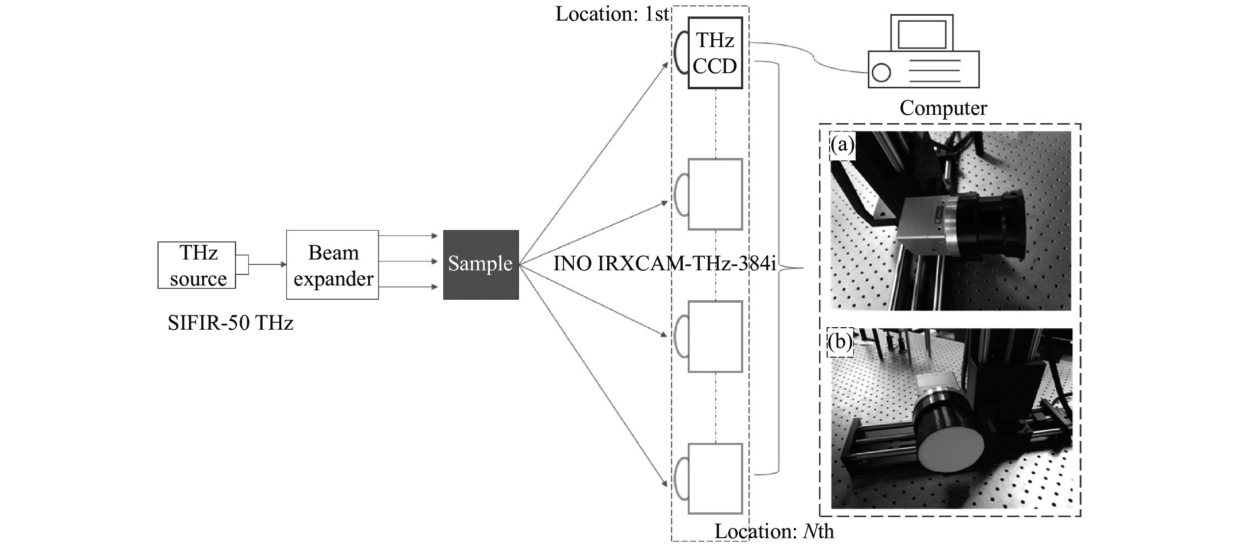
Figure 1. Schematic diagram of the system. (a) The THz camera and the two-dimensional translation stage; (b) the light filter.

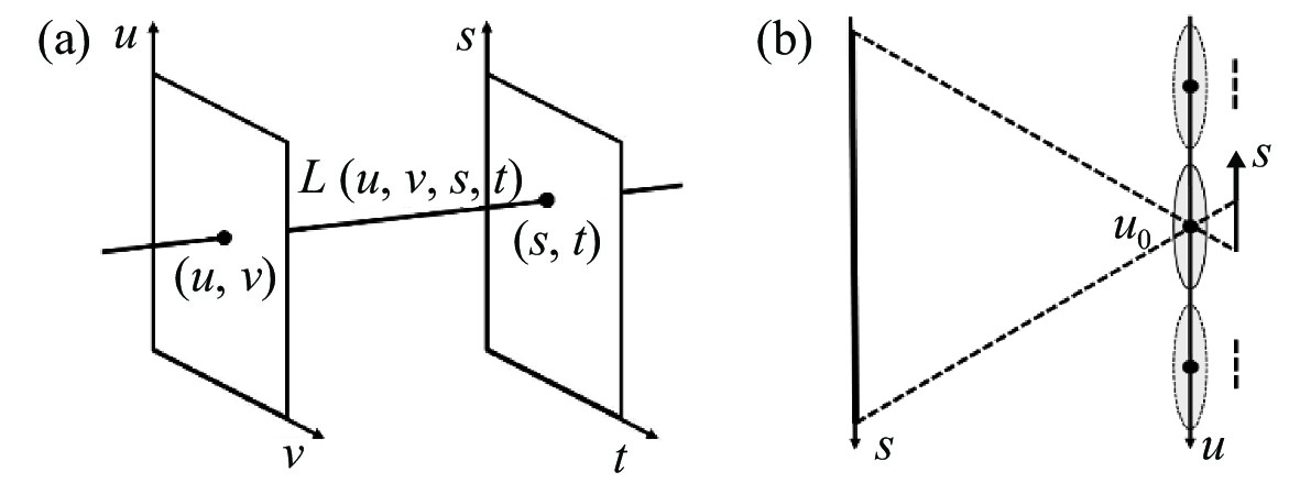
Figure 2. Parametrization of the light field. (a) Pairs of points on two parallel planes; (b) parameterization of our system

Figure 3. The resampling diagram of refocusing process. When changing the object distance, the spatial coordinate S of the reference sub-image u0 are constant, while the corresponding object point moves from P to Pα. According to the geometric principles, we can calculate the new coordinate Sα of sub-image u, which is different from the coordinate S1 corresponding to P

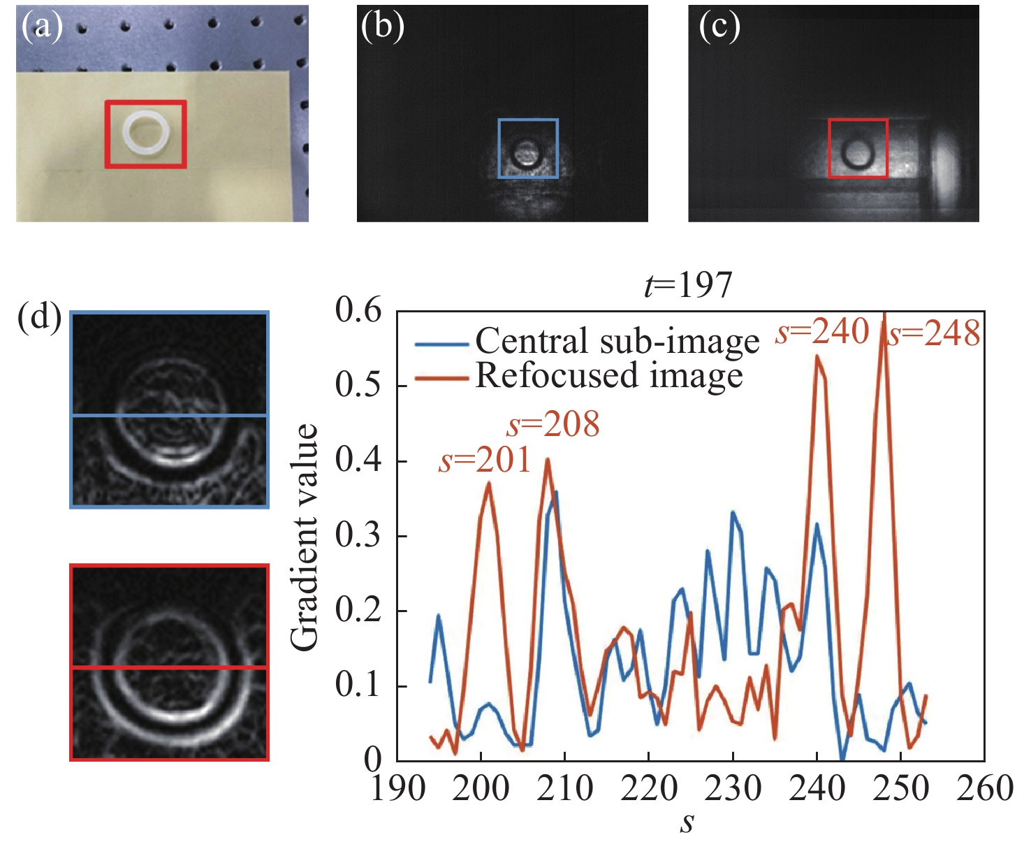
Figure 4. A rubber ring in an envelope (grid size 9×3, Du=Dv=10 mm). (a) The rubber ring (outer diameter is 25 mm; inner diameter is 17 mm) and the envelope; (b) the reference sub-image (u=4, v=2); (c) the refocused image (αL=720 mm); (d) normalized gradient image of the labelled regions of (b) and (c), respectively and their gradient values of labelled horizontal lines corresponding to t=197

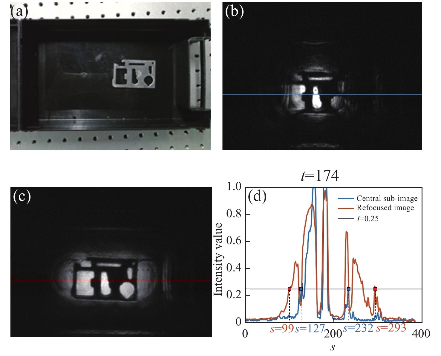
Figure 5. A steel board with hollowed parts in a plastic box (grid size 9×1, Du=10 mm). (a) The steel board (length is 68 mm; width is 45 mm) and the plastic box; (b) the reference sub-image (u=5, v=1); (c) the refocused image (αL=730 mm); (d) intensity of labelled horizontal lines corresponding to t=174

Figure 6. Metal wrenches fixed on a polyvinyl chloride(PVC) board by tape. (grid size 9×7, Du=Dv=10 mm) (a) the wrenches (from left to right the diameters are 0.7 mm, 0.9 mm, 1.3 mm and 1.5 mm) and the PVC board; (b) the reference sub-image (u=3, v=4); (c) the refocused image (αL=680 mm); (d) the refocused image after histogram equalization.

Figure 7. Metal wrenches (fixed camera and moving target, grid size 9×5, Du=Dv=10 mm). (a) The wrenches and the PVC board; (b) the reference sub-image (u=5, v=3); (c) the refocused image (αL=700 mm); (d) the refocused image after histogram equalization

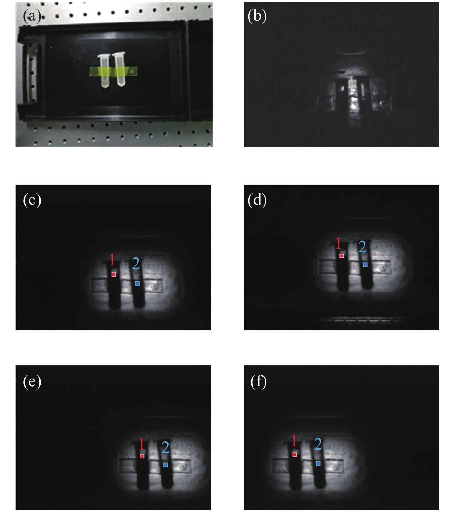
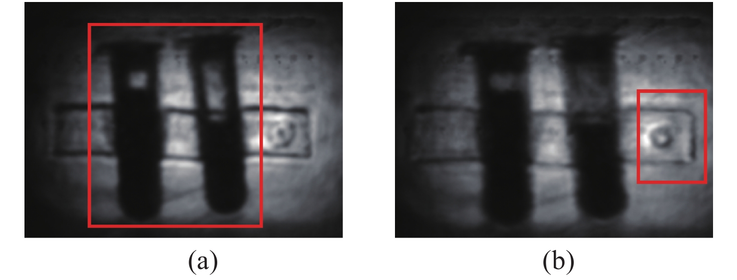
Figure 8. Refocusing images of different sub-views (two PVC bottles with liquid fixed by tape in a high-density polyethylene plastic box, grid size 9×2, Du=10 mm, Dv=20 mm). (a) The bottles (length is 50 mm; diameter is 13 mm; thickness is 2 mm) and the plastic box; (b) one primitive sub-image; (c)(d)(e)(f) are the refocused images with angular coordinates (4,1), (4,2), (1,1) and (9,1) respectively (αL=720 mm).

Figure 9. Refocusing images of different depths. (a) The image focused on the bottles, αL=720 mm. (b) The image focused on the tape and the plastic box, αL=670 mm

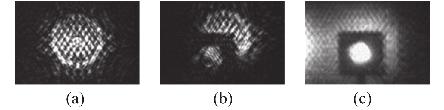
Figure 10. A steel holed cube blocked by a piece of wire mesh placed between it and the THz camera. (a) and (b) are two primitive sub-images showing the wire mesh and the obscured target respectively; (c) the refocused image
Table 1. Coordinates of sample pixels in different sub-views
Sub-view (4,1) (4,2) (1,1) (9,1) Pixel 1 (192,175) (192,138) (248,175) (99,175) Pixel 2 (238,193) (238,156) (295,193) (145,193)  下载: 导出CSV
-
[1] ZHANG Y D, DENG C, SUN W F, et al. Terahertz continuous-wave transmission imaging system and its application in security inspections[J]. Proceedings of SPIE, 2008, 6840: 684010. [2] MITTLEMAN D M. Twenty years of terahertz imaging [Invited][J]. Optics Express, 2018, 26(8): 9417-9431. doi: 10.1364/OE.26.009417 [3] YAO J Q, LU Y, ZHANG B G, et al. New research progress of THz radiation[J]. Journal of Optoelectronics·Laser, 2005, 16(4): 503-510. [4] LEE A W, HU Q. Real-time, continuous-wave terahertz imaging by use of a microbolometer focal-plane array[J]. Optics Letters, 2005, 30(19): 2563-2565. doi: 10.1364/OL.30.002563 [5] KARPOWICZ N, ZHONG H, ZHANG C L, et al. Compact continuous-wave subterahertz system for inspection applications[J]. Applied Physics Letters, 2005, 86(5): 054105. doi: 10.1063/1.1856701 [6] VALUŠIS G, LISAUSKAS A, YUAN H, et al. Roadmap of terahertz imaging 2021[J]. Sensors, 2021, 21(12): 4092. doi: 10.3390/s21124092 [7] YANG J, RUAN SH CH, ZHANG M, et al. Real-time continuous-wave imaging with a 1.63THz OPTL and a pyroelectric camera[J]. Optoelectronics Letters, 2008, 4(4): 295-298. doi: 10.1007/s11801-008-8036-0 [8] XIAO H, ZHU F. Identification of dangerous goods in human THZ images[C]. Proceedings of the 2018 International Conference on Network, Communication, Computer Engineering (NCCE 2018), Atlantis Press, 2018: 899-903. [9] WOODWARD R M, WALLACE V P, ARNONE D D, et al. Terahertz pulsed imaging of skin cancer in the time and frequency domain[J]. Journal of Biological Physics, 2003, 29(2-3): 257-259. [10] TAO Y H, FITZGERALD A J, WALLACE V P. Non-contact, non-destructive testing in various industrial sectors with terahertz technology[J]. Sensors, 2020, 20(3): 712. doi: 10.3390/s20030712 [11] WONG T M, KAHL M, BOLIVAR P H, et al. . Frequency Modulated Continuous Wave (FMCW) THz Image 3D Superresolution[Z]. arXiv: 1802.05457v1, 2018. [12] LEVOY M. Light fields and computational imaging[J]. Computer, 2006, 39(8): 46-55. doi: 10.1109/MC.2006.270 [13] WU G CH, MASIA B, JARABO A, et al. Light field image processing: an overview[J]. IEEE Journal of Selected Topics in Signal Processing, 2017, 11(7): 926-954. doi: 10.1109/JSTSP.2017.2747126 [14] FANG L, DAI Q H. Computational light field imaging[J]. Acta Optica Sinica, 2020, 40(1): 0111001. doi: 10.3788/AOS202040.0111001 [15] YIN Y K, YU K, YU CH ZH, et al. 3D imaging using geometric light field: a review[J]. Chinese Journal of Lasers, 2021, 48(12): 1209001. (in Chinese) [16] LI Y, WANG X, ZHOU G, et al. Overview of 4D Light Field Representation[J]. Laser &Optoelectronics Progress, 2021, 58(18): 1811012. (in Chinese) [17] TIAN Y, ZENG H Q, HOU J H, et al. Light field image quality assessment via the light field coherence[J]. IEEE Transactions on Image Processing, 2020, 29: 7945-7956. doi: 10.1109/TIP.2020.3008856 [18] COUILLAUD J, ZIOU D. Light field variational estimation using a light field formation model[J]. The Visual Computer, 2020, 36(2): 237-251. doi: 10.1007/s00371-018-1599-2 [19] YAO T, SANG X ZH, WANG P, et al. Depth reconstruction for 3D light-field display based on axially distributed light field[J]. Optical Engineering, 2021, 60(5): 053103. [20] ZHOU G, LI S, LAM E Y. Light field image restoration in low-light environment[J]. Proceedings of SPIE, 2020, 11525: 115251H. [21] GUO C L, JIN J, HOU J H, et al. . Accurate light field depth estimation via an occlusion-aware network[C]. IEEE International Conference on Multimedia and Expo (ICME), IEEE, 2020. [22] JAIN R, GRZYB J, PFEIFFER U R. Terahertz light-field imaging[J]. IEEE Transactions on Terahertz Science and Technology, 2016, 6(5): 649-657. [23] LYU N F, ZUO J, ZHAO Y M, et al. Terahertz synthetic aperture imaging with a light field imaging system[J]. Electronics, 2020, 9(5): 830. doi: 10.3390/electronics9050830 [24] LYU N F, ZUO J, ZHAO Y M, et al. Layer-resolving terahertz light-field imaging based on angular intensity filtering method[J]. Sensors, 2021, 21(22): 7451. doi: 10.3390/s21227451 -

 下载:
下载:


计量
- 文章访问数: 837
- HTML全文浏览量: 589
- PDF下载量: 189
- 被引次数: 0
