Preliminary design and analysis of telescope for space gravitational wave detection
-
摘要: 引力波的直接观测已开启引力波天文学的新篇章,爱因斯坦的百年预言终获证实。空间引力波探测器使得探测0.1 mHz~1 Hz频段丰富的引力波源成为可能,与地面引力波探测器互为补充,才可实现更加宽广波段的引力波探测,揭开宇宙早期的更多秘密。空间激光干涉引力波探测采用外差干涉测量技术,测量间距百万公里的两自由悬浮测试质量间10 pm量级的变化量。望远镜是激光干涉测量系统的重要组成部分,1 pm的光程稳定性及苛刻的杂散光要求,不同于传统的几何成像望远镜。本文根据空间太极计划任务需求,对望远镜的功能及技术要求进行了分析,并完成了原理样机的初步方案设计,针对百万公里远场波前分布,分析了望远镜系统的敏感性,同时完成了在轨光机热集成仿真,为后面原理样机的研制奠定了技术基础。Abstract: The direct detection of gravitational waves opens up a new era of gravitational wave astronomy, and 100-year-old prediction on gravitational wavers by Einstein have been confirmed ultimately. The space gravitational wave detector makes it possible to detect rich sources of gravitational waves in the 0.1 mHz-1 Hz band. The space gravitational wave detector and the ground gravitational wave detector complement each other, and the combination of the two methods can realize the detection of gravitational waves in a broader band, thus uncovering more secrets of the early universe. Spatial laser interferometry gravitational wave detection uses heterodyne interferometry to measure changes in the order of 10 pm between two free-floating test masses that are millions of kilometers apart. Telescope is an important part of the laser interferometry system. Unlike the traditional geometrical imaging telescope, the telescope of the laser interferometry system shall meet the requirements of optical path stability for 1 pm and that of a harsh stray light. Based on the mission requirements of the Taiji Program in Space, this paper analyzes the functions and technical requirements of the telescope and completes the preliminary design of the principle prototype. In this paper, the sensitivity of the telescope system is analyzed according to the wavefront distribution in the far field of one million kilometers. At the same time, the thermal integration simulation in orbit is completed, which lays the technical foundation for the development of the subsequent principle prototypes.
-
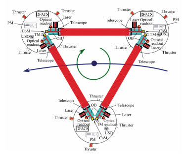
图 1 空间引力波探测天文台,三个航天器构成等边三角形,通过端点航天器间的激光链路来测量位于端点的测试质量间距离的变化[3]
Figure 1. A space-based gravitational wave observatory, consists of an equilateral triangle of three spacecraft with laser links between endpoint spacecraft, to measure the change in the distance between the test masses at the endpoint[3]
图 2 LISA轨道及航天器编队示意图,航天器组成的平面与黄道面夹角约为60°, 航天器星座质心落后地球约20°,航天器之间的距离为5×10⁶ km[3]
Figure 2. Schematic diagram of LISA orbit and spacecraft formation. The angle between the spacecraft plane and the ecliptic plane is about 60°. The constellation trails earth by about 20°, and the distance between spacecraft is 5×10⁶ km[3]
图 3 引力波经过测试质量组成的三角形编队。三角形编队中3个测试质量代表3个LISA航天器,红色臂长的时变量即需要测量的引力波引起的距离变化量[1]
Figure 3. Gravity waves pass through the triangle formation formed by the test masses. The three test masses in formation represent three LISA spacecraft, the time variable of the red arm length represents the distance variation caused by the gravitational wave that needs to be measured
表 1 望远镜关键技术指标
Table 1. Key technology requirements of telescope
Characteristics Requirements Aperture 20 cm Optical efficiency ≥0.853 Field of view acquisition mode 400μrad full angle Science mode(out of plane) ±7 μrad (in plane) ±4.2 μrad in-plane Optical path length stability 
Magnification 40 Far-field wavefront quality λ/20 表 2 望远镜结构参数变化量
Table 2. Variations of telescope parameters
Type of variations Variations M1 M2 M3 M4 position X decenter/μm 0.5 0.5 0.5 0.5 Y decenter/μm 0.5 0.5 0.5 0.5 Z decenter/μm 0.5 0.5 0.5 0.5 X tilt/(″) 0.4 0.4 0.4 0.4 Y tilt/(″) 0.2 0.4 0.4 0.4 Z tilt/(″) 0.4 0.4 - - surface Radius/μm 1 1 1 1 Conic 0.00001 0.001 - - 表 3 5×10⁶ km处远场波前变化量PV值
Table 3. Far field wavefront variations(PV) at 5×10⁶ km
Type of variations Variations Variation PV(λ) M1 M2 M3 M4 position X decenter/μm 8.26×10⁻⁶ 1.12×10⁻⁶ 1.33×10⁻⁶ 1.47×10⁻⁶ Y decenter/μm 4.34×10⁻⁷ 5.35×10⁻⁸ 1.05×10⁻⁷ 2.93×10⁻⁶ Z decenter/μm 4.04×10⁻⁷ 1.47×10⁻⁶ 1.31×10⁻⁷ 2.70×10⁻⁸ X tilt/(″) 3.33×10⁻⁶ 1.31×10⁻⁶ 1.10×10⁻⁶ 6.16×10⁻⁷ Y tilt/(″) 2.42×10⁻⁷ 5.91×10⁻⁸ 7.94×10⁻⁷ 6.61×10⁻⁸ Z tilt/(″) 3.46×10⁻⁹ 1.30×10⁻⁶ - - surface Radius/mm 8.86×10⁻⁷ 1.87×10⁻⁶ 1.26×10⁻⁷ 1.99×10⁻⁸ Conic 4.07×10⁻⁷ 1.06×10⁻⁶ - - 表 4 各反射镜的平动和转动
Table 4. Translaton and rotation of mirrors
M1 M2 M3 M4 PV/nm 45.721 1.663 0.121 0.711 RMS/nm 8.927 0.503 0.032 0.183 ΔX/μm 0.001 -0.369 -0.005 -0.024 ΔY/μm -0.403 0.977 0.497 -1.271 ΔZ/μm 0.855 1.407 0.540 -0.988 Δθx/(″) -0.363 -0.009 2.570 2.063 Δθy/(″) 0.104 -0.403 0.011 0.027 -
[1] KARSTEN D. LISA(Unveiling a hidden Universe) Assessment Study Report[R]. ESA/SRE, 2011, 3. doi: 10.1007/s10714-014-1793-0 [2] JEFFREY C L, SHANNON R S. Optical telescope system-level design considerations for a space-based gravitational wave mission[J]. SPIE, 2011, 9904:99041K. https://ntrs.nasa.gov/search.jsp?R=20170003764 [3] OTTO M. Time-delay interferometry simulations for the laser interferometer space antenna[D]. Hannover: Max Planck Institute for Gravitational Physics, 2015. https://www.osapublishing.org/oe/abstract.cfm?uri=oe-19-17-15937 [4] 罗子人, 白姗, 边星, 等.空间激光干涉引力波探测[J].力学进展, 2013, 43(4):415-447. doi: 10.6052/1000-0992-13-044LUO Z R, BAI SH, BIAN X, et al.. Gravitational wave detection by space laser interferometry[J]. Advances in Mechanics, 2013, 43(4):415-447.(in Chinese) doi: 10.6052/1000-0992-13-044 [5] 戚子文, 刘炳国, 张仲海, 等.双点干涉法位相缺陷检测中的解相算法比较[J].中国光学, 2016, 9(4):483-490. http://www.chineseoptics.net.cn/CN/abstract/abstract9439.shtmlQI Z W, LIU B G, ZHANG ZH H, et al. Comparison of phase extraction algorithms in testing of phase defects with two-point interference[J]. Chinese Optics, 2016, 9(4):483-490.(in Chinese) http://www.chineseoptics.net.cn/CN/abstract/abstract9439.shtml [6] 王智, 马军, 李静秋, 等.空间引力波探测计划-LISA系统设计要点[J].中国光学, 2015, 8(6):980-987. http://www.chineseoptics.net.cn/CN/abstract/abstract9334.shtmlWANG ZH, MA Jun, LI J Q, et al.. Space-based gravitational wave detection mission: design highlights of LISA system[J]. Chinese Optics, 2015, 8(6):980-987.(in Chinese) http://www.chineseoptics.net.cn/CN/abstract/abstract9334.shtml [7] MARCELLO S. Payload preliminary design description[R]. LISA-MSE-DD-0001, Issue 1, rev 1, 2009. [8] OLIVER J. NGO(Revealing a hidden Universe: opening a new chapter of discovery) Assessment Study Report[R]. ESA/SRE(2011)19, December 2011. doi: 10.1007/s11431-015-5770-y [9] BENDER P, BRILLET A. LISA Pre-phase A Report[R]. Max-Planck-Institut for Quantenoptic, 1998. https://www.yumpu.com/en/document/view/11462402/pre-phase-a-report-lisa-nasa [10] BENDER P L. Wavefront distortion and beam pointing for LISA[J]. Class. Quantum Grav, 2005, 22(S):339-346. https://www.researchgate.net/publication/243412646_Wavefront_distortion_and_beam_pointing_for_LISA [11] SANKAR S, LIVAS J. Testing and characterization of a prototype telescope for the evolved Laser Interferometer Space Antenna(eLISA)[J]. SPIE, 9904:99045A. https://www.spiedigitallibrary.org/redirect/proceedings/proceeding?doi=10.1117/12.2233075 [12] VERLAAN A L, HOGENHUIS H, PIJNENBUR G J, et al.. LISA telescope assembly optical stability characterization for ESA[J]. SPIE, 2012, 8450, 845003. https://www.spiedigitallibrary.org/redirect/proceedings/proceeding?doi=10.1117/12.925112 [13] LIVAS J, SANKAR S. Optical telescope design study results[J]. J. Physics:Conference Series, 2015, 610:012029. doi: 10.1088/1742-6596/610/1/012029 [14] 宋同消. 空间引力波探测中激光波前误差分析[D]. 北京: 首都师范大学, 2013. http://cdmd.cnki.com.cn/Article/CDMD-10028-1013289485.htmSONG T X. Analysis of wavefront distortion in detection of gravitational wave in space[D]. Beijing: Capital Normal University, 2013. (in Chinese) http://cdmd.cnki.com.cn/Article/CDMD-10028-1013289485.htm [15] 杨帅, 沙巍, 陈长征, 等.空间相机碳纤维框架的设计与优化[J].光学精密工程, 2017, 25(3):697-705. https://mall.cnki.net/qikan-HWYJ201407032.htmlYANG SH, SHA W, CHEN CH ZH, et al.. Design and optimization of carbon fiber framework for space camera[J]. Opt. Precision Eng., 2017, 25(3):697-705.(in Chinese) https://mall.cnki.net/qikan-HWYJ201407032.html -


 下载:
下载:


