


Simulation analysis of isolation between laser communication ground test equipments
-
摘要: 受空间所限,激光通信地面测试平台与被测终端之间的距离远小于实际通信距离,导致测试平台光机等器件产生的后向散射杂光进入被测终端,从而严重影响被测终端的测试性能。从被测终端与测试平台间的光学干扰问题出发,本文研究了被测终端与测试平台间隔离度的关系,分别设计了卡塞格林和离轴三反光学天线,并根据杂散光传输模型,采用杂散光分析软件分析了光学天线结构形式及表面粗糙度两方面对隔离度的影响。分析结果表明,采用离轴三反光学天线时的隔离度明显高于卡塞格林光学天线,且隔离度随着光学表面粗糙度的减小而增大,当光学表面的粗糙度达到0.892 nm时,隔离度可达−86.22 dB。最后,推导了ABg模型与Harvey模型参数间的关系,并根据粗糙度与TIS计算公式,得出粗糙度分别为0.7 nm及0.5 nm的ABg模型参数,它们的终端间隔离度分别为−94.39 dB和−97.3 dB,实现了−90 dB的隔离度指标。Abstract: The distance between a laser communication ground test platform and the terminal under test is far less than the actual communication distance due to space limitations. As a result, the backscattered stray light generated by the test platform optical device will enter the terminal under test, and the signal will seriously affect the performance of the terminal under test. Aiming at this problem, we research the isolation relationship between the tested terminal and the test platform based on the optical interference problem. The Cassegrain and off-axis three-mirror optical antenna are designed respectively. According to astigmatic transmission model, the stray light analysis software is employed to analyze the influence of optical antenna's structure and surface roughness on the isolation. The results of the analysis show that the isolation when applying the off-axis three-mirror optical antenna is significantly higher than that applying the Cassegrain optical antenna, and that this isolation increases with a decrease in the roughness of the optical surface. When the optical surface's roughness reaches 0.892 nm, the isolation is −86.22 dB. Finally, the relationship between the ABg model and the Harvey model parameters is derived. According to calculation formula of the roughness and TIS, the ABg model parameters with roughness of 0.7 nm and 0.5 nm are theoretically obtained. The isolation between the terminals is −94.39 dB and −97.3 dB, achieving an isolation rating of −90 dB.
-
Key words:
- laser communication /
- optical antenna /
- isolation /
- surface scattering model /
- stray light
-
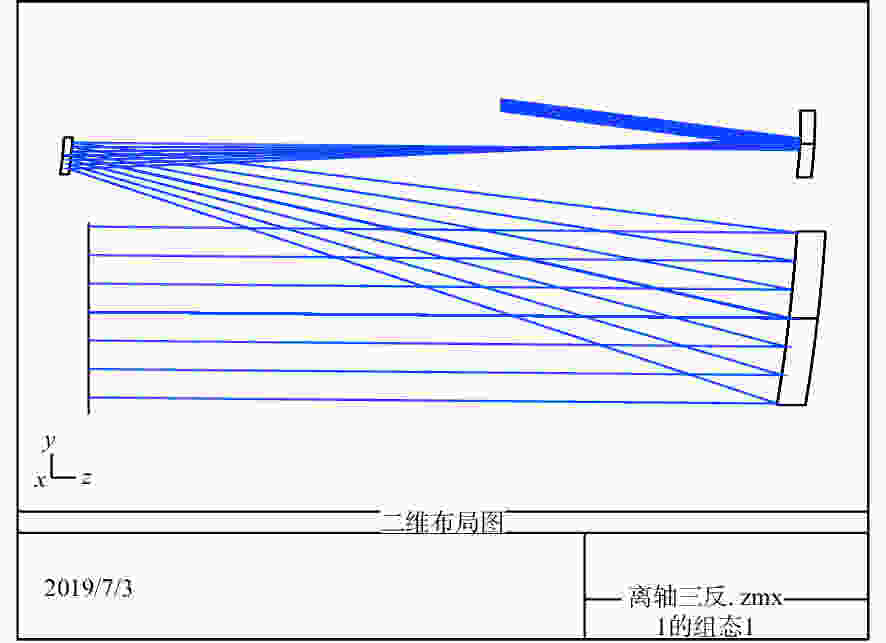
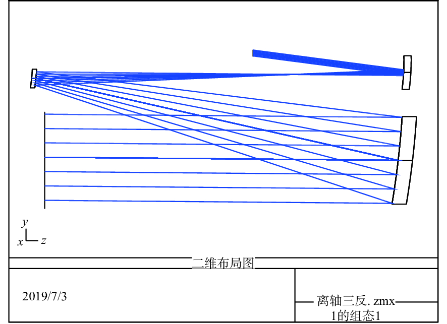
图 4 离轴三反光学天线二维布局图
Figure 4. Two-dimensional layout of off-axis three-mirror optical antenna

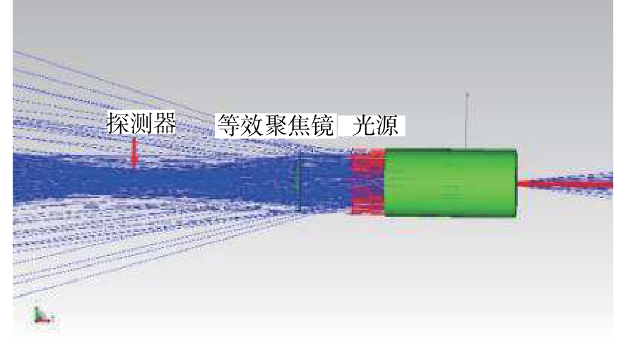
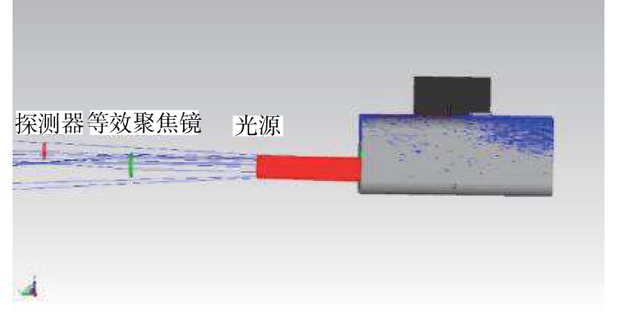
图 7 离轴三反光学天线的杂散光模拟
Figure 7. Stray light simulation of off-axis three-mirror optical antenna
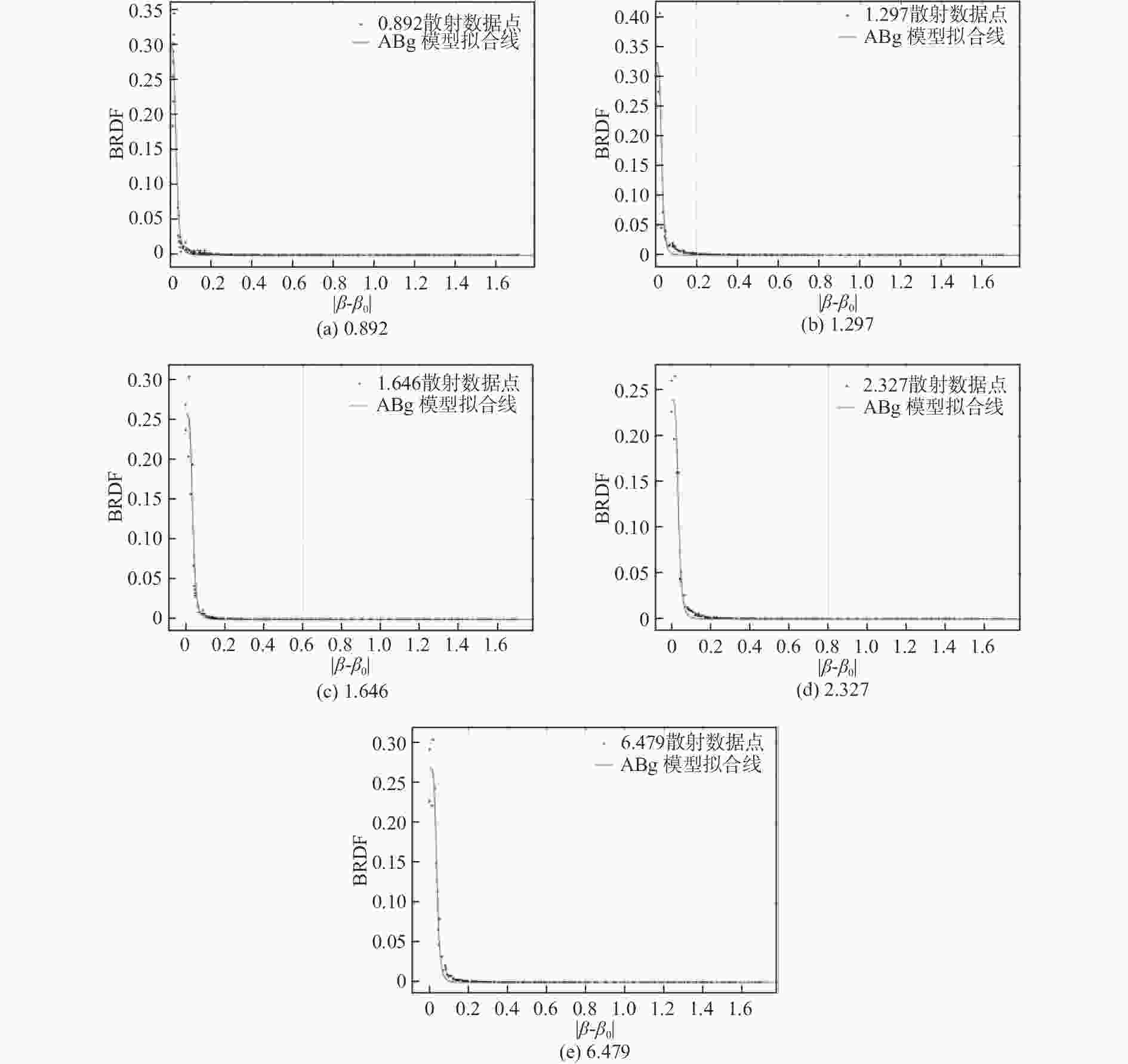
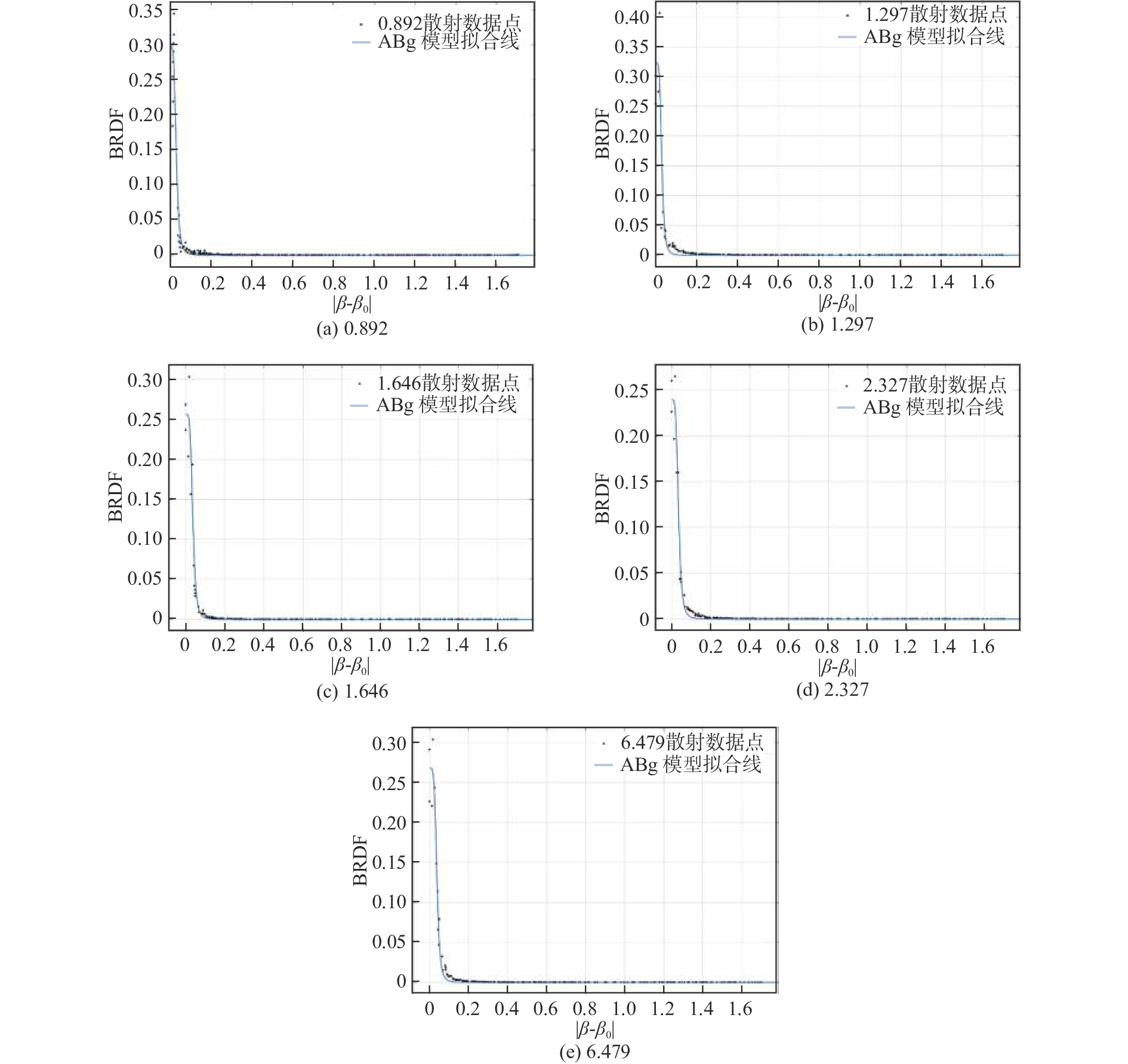
图 9 不同粗糙度镀膜基片的散射数据拟合曲线
Figure 9. Scattering fitting curves of coated substrate with different roughnesses
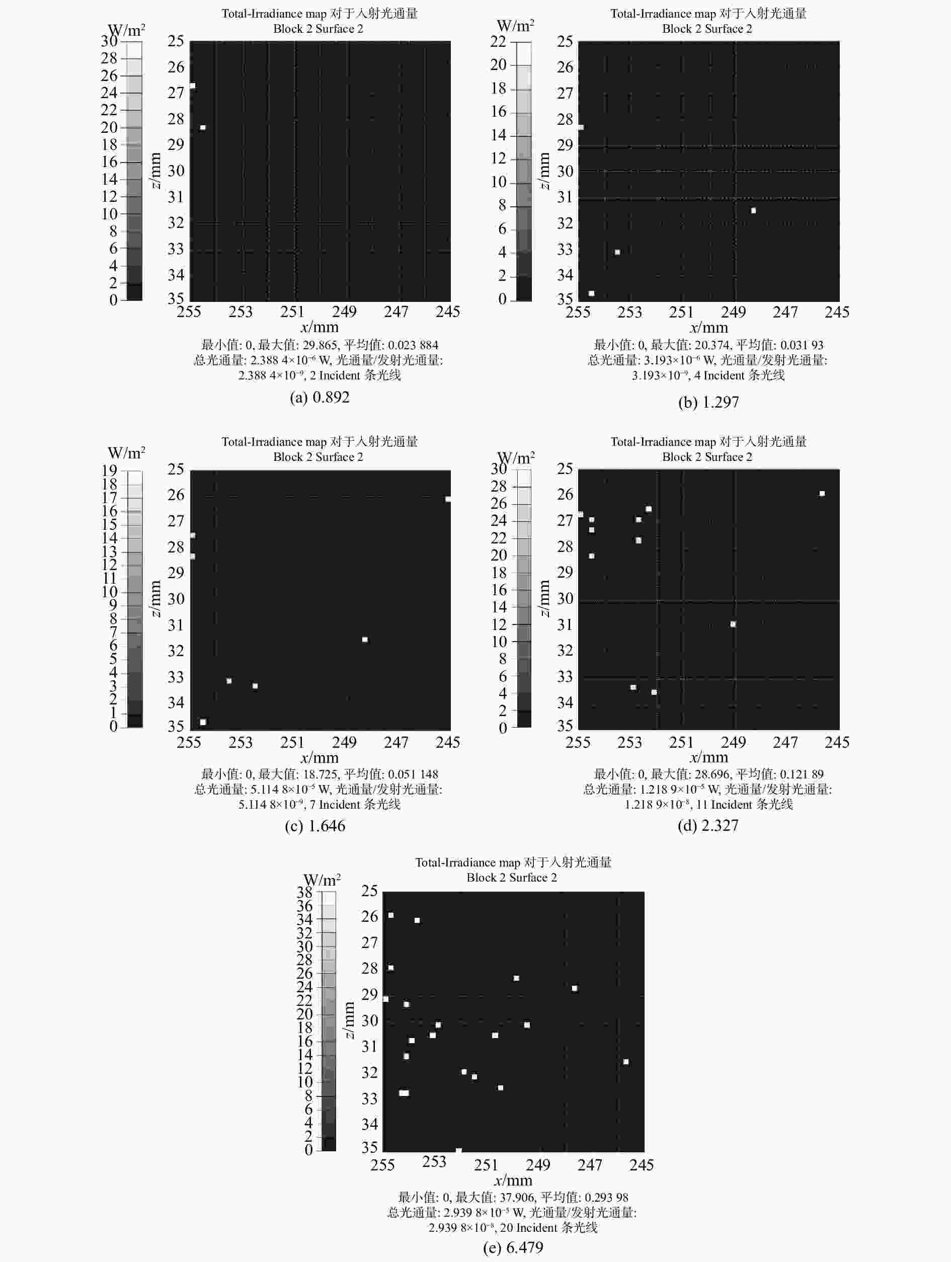
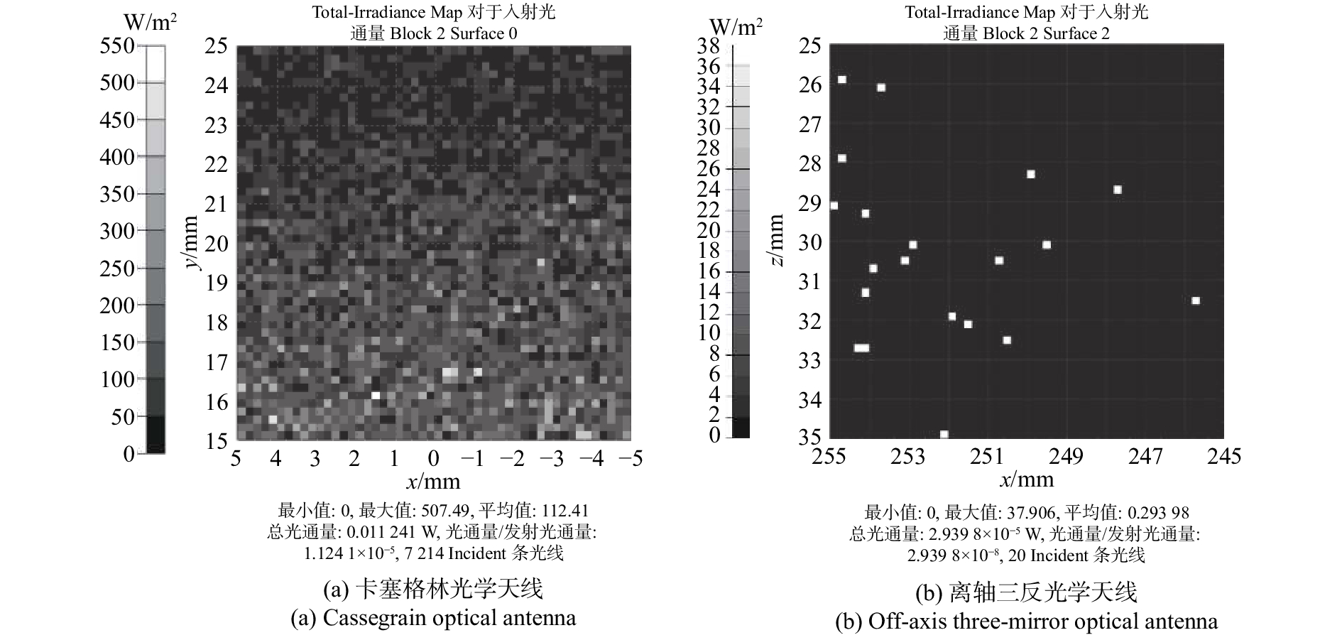
图 10 采用不同粗糙度反射镜时探测器的光通量图
Figure 10. Detector′s luminous flux maps when applying reflectors with different roughnesses
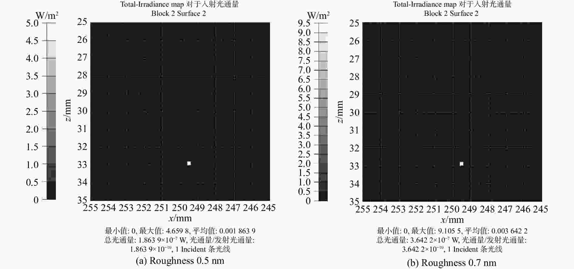
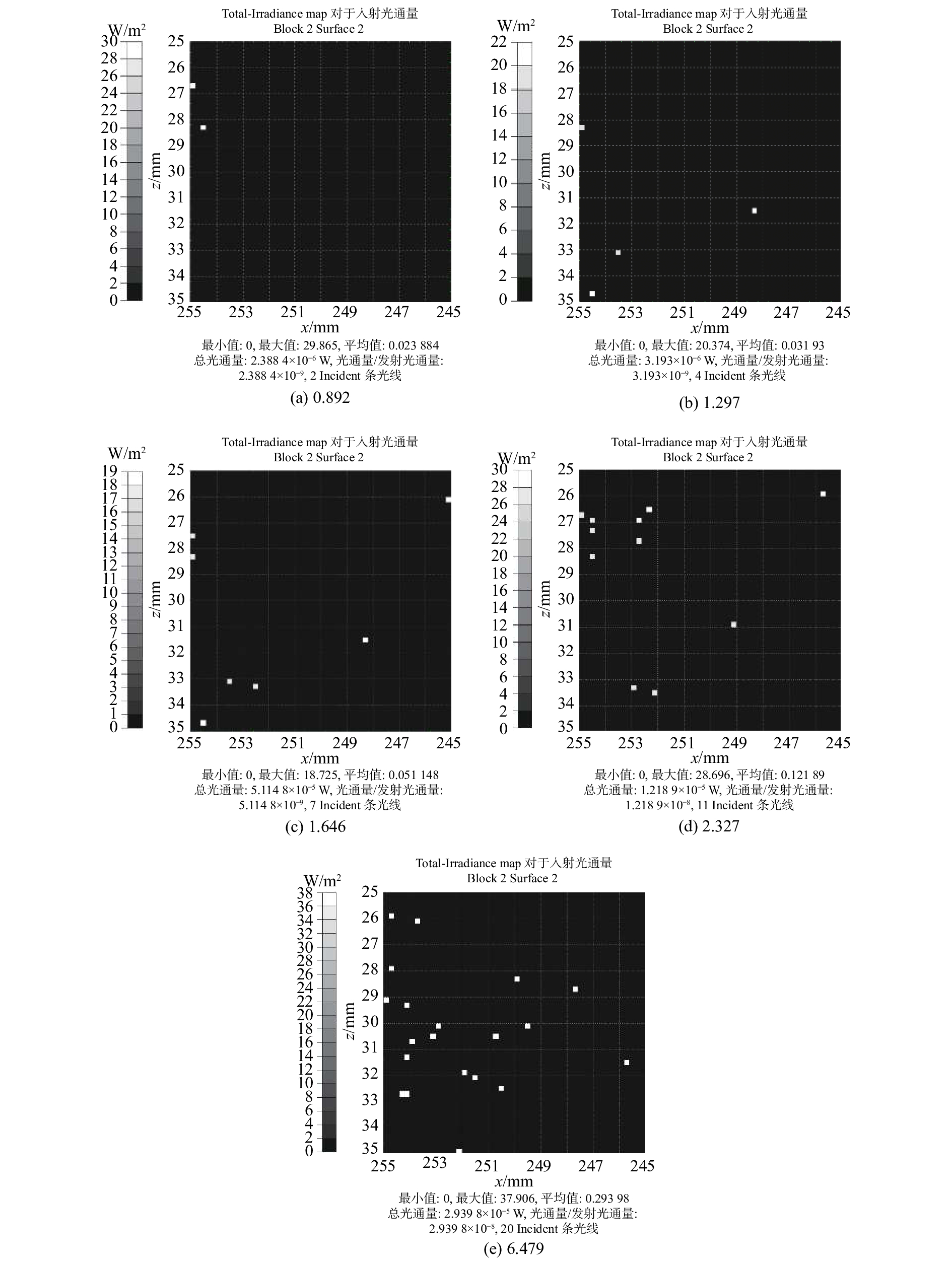
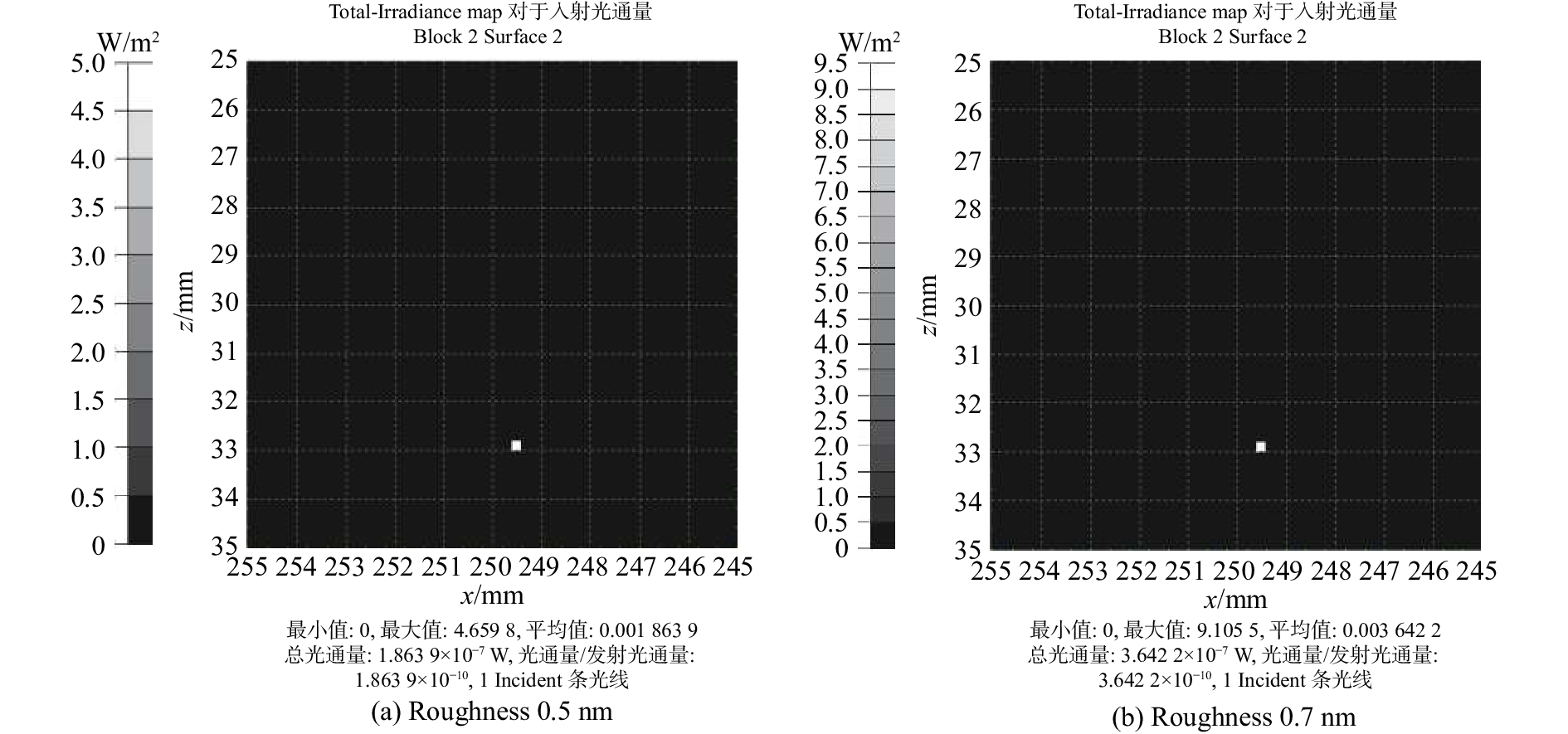
图 11 低粗糙度下探测器的光通量图
Figure 11. Luminous flux maps of detector when applying low roughness reflector
表 1 光学天线的设计指标
Table 1. Design specifications of optical antenna
指标名称 参数值 测试波长/nm 632.8 望远镜放大倍率 15±0.1 望远镜主口径/mm ≥610 有效视场/mrad ≥±6 像质要求 中心视场:0.033λ(rms)、0.25λ(PV) 边缘视场:0.050λ(rms)、0.33λ(PV)  下载: 导出CSV
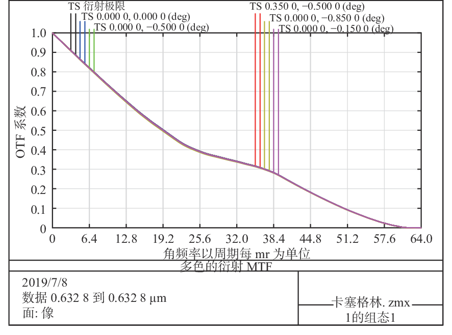
表 2 卡塞格林光学天线波像差
Table 2. Wave aberration of Cassegrain optical antenna
波段(μm) 项目 视场 中心视场 边缘视场 0.632 8($\lambda $) 波像差 P-V 0.033 8$\lambda $ 0.143 7$\lambda $ RMS 0.006 5$\lambda $ 0.032 4$\lambda $ 斯特尔比 0.999 8 0.999 7
下载: 导出CSV
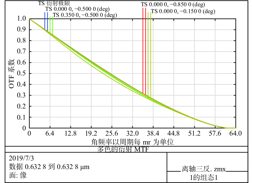
表 3 离轴三反光学天线波像差
Table 3. Wave aberration of off-axis three-mirror optical antenna
波段(μm) 项目 视场 中心视场 边缘视场 0.632 8($\lambda $) 波像差 P-V 0.037$\lambda $ 0.140$\lambda $ RMS 0.009$\lambda $ 0.024$\lambda $ 斯特尔比 0.998 0.987
下载: 导出CSV
表 4 两种光学天线的隔离度对比
Table 4. Comparison of isolation between two optical antennas
光学天线类型 进入探测器的杂光数目 光通量大小(W) 隔离度(dB) 卡塞格林 7 214 0.011 24 −49.49 离轴三反 20 2.94 × 10⁻⁵ −75.32
下载: 导出CSV
表 5 具有不同粗糙度镀膜基片的散射数据的ABg模型拟合参数
Table 5. ABg model fitting parameters of scattering data of coated substrate with different roughnesses
粗糙度(nm) A B g RMSE 0.892 2.15$\times10^{-8} $ 7.51$\times10^{-8} $ 4.624 0.008 798 1.297 2.47$\times10^{-8} $ 7.93$\times10^{-8} $ 4.389 0.001 32 1.646 1.34$\times10^{-8} $ 5.37$\times10^{-8} $ 4.986 0.007 629 2.327 1.17$\times10^{-7} $ 4.92$\times10^{-7} $ 4.290 0.005 674 6.479 1.01$\times10^{-7} $ 3.81$\times10^{-7} $ 4.503 0.006 217
下载: 导出CSV
表 6 采用不同粗糙度反射镜对应的隔离度
Table 6. Isolations when applying reflectors with different roughnesses
粗糙度 进入探测器的杂光数目 杂光光通量大小(W) 隔离度(dB) 0.892 2 2.39$\times10^{-6} $ −86.22 1.297 4 3.19$\times10^{-6} $ −84.96 1.646 7 5.11$\times10^{-6} $ −82.92 2.327 11 1.22$\times10^{-5} $ −79.14 6.479 20 2.94$\times10^{-5} $ −75.32
下载: 导出CSV
表 7 采用低粗糙度反射镜时对应的隔离度
Table 7. Isolations when applying low roughness reflector
粗糙度
(nm)进入探测器的
杂光数目杂光光通量
大小(W)隔离度
(dB)0.5 1 1.86$\times10^{-7} $ −97.30 0.7 1 3.64$\times10^{-7} $ −94.39
下载: 导出CSV
-
[1] 吴从均, 颜昌翔, 高志良. 空间激光通信发展概述[J]. 中国光学,2013,6(5):670-680.WU C J, YAN CH X, GAO ZH L. Overview of space laser communications[J]. Chinese Optics, 2013, 6(5): 670-680. (in Chinese) [2] 高铎瑞, 李天伦, 孙悦, 等. 空间激光通信最新进展与发展趋势[J]. 中国光学,2018,11(6):901-913. doi: 10.3788/co.20181106.0901GAO D R, LI T L, SUN Y, et al. Latest developments and trends of space laser communication[J]. Chinese Optics, 2018, 11(6): 901-913. (in Chinese) doi: 10.3788/co.20181106.0901 [3] 田媛. 空间链路模拟器设计和实验标定[D]. 长春: 中国科学院研究生院长春光学精密机械与物理研究所, 2014.TIAN Y. Optical design and experimental calibration for the space link model system[D]. Changchun: Changchun Institute of Optics, Fine Mechanics and Physics, Chinese Academy of Sciences, 2014. (in Chinese) [4] 吴从均. 星间激光通信终端及其实验室检测平台光学系统研究[D]. 长春: 中国科学院长春光学精密机械与物理研究所, 2014.WU C J. Study of inter-satellites laser communication terminals and its laboratory testing platform's optical system[D]. Changchun: Changchun Institute of Optics, Fine Mechanics and Physics, Chinese Academy of Sciences, 2014. (in Chinese) [5] 杨成龙, 颜昌翔, 杨宇飞. 星间激光通信终端光学天线的隔离度[J]. 中国光学,2017,10(4):462-468. doi: 10.3788/co.20171004.0462YANG CH L, YAN CH X, YANG Y F. Isolation of optical antenna of inter-satellites laser communication terminals[J]. Chinese Optics, 2017, 10(4): 462-468. (in Chinese) doi: 10.3788/co.20171004.0462 [6] BIRKL R A, MANHART S. Back-reflection measurements on the SILEX telescope[J]. Proceedings of SPIE, 1991, 1522: 252-258. doi: 10.1117/12.46083 [7] 朱杨. 空间光学系统杂散辐射抑制研究[D]. 长春: 中国科学院研究生院长春光学精密机械与物理研究所, 2016.ZHU Y. Research on stray radiation suppression of space optical system[D]. Changchun: Changchun Institute of Optics, Fine Mechanics and Physics, Chinese Academy of Sciences, 2016. (in Chinese) [8] 石栋梁. 基于BRDF的光机系统杂散辐射研究[D]. 哈尔滨: 哈尔滨工业大学, 2014.SHI D L. Research on stray light of optical and mechanical system based on BRDF[D]. Harbin: Harbin Institute of Technology, 2014. (in Chinese) [9] 宋延松, 杨建峰, 李福, 等. 基于杂散光抑制要求的光学表面粗糙度控制方法研究[J]. 物理学报,2017,66(19):194201. doi: 10.7498/aps.66.194201SONG Y S, YANG J F, LI F, et al. Method of controlling optical surface roughness based on stray light requirements[J]. Acta Physica Sinica, 2017, 66(19): 194201. (in Chinese) doi: 10.7498/aps.66.194201 [10] 陈醒, 胡春晖, 颜昌翔, 等. 大视场空间可见光相机的杂散光分析与抑制[J]. 中国光学,2019,12(3):678-685. doi: 10.3788/co.20191203.0678CHEN X, HU CH H, YAN CH X, et al. Analysis and suppression of space stray light of visible cameras with wide field of view[J]. Chinese Optics, 2019, 12(3): 678-685. (in Chinese) doi: 10.3788/co.20191203.0678 [11] 金光, 李艳杰, 钟兴, 等. 空间成像与激光通信共口径光学系统设计[J]. 光学 精密工程,2014,22(8):2067-2074. doi: 10.3788/OPE.20142208.2067JIN G, LI Y J, ZHONG X, et al. Design of co-aperture optical system for space imaging and laser communication[J]. Optics Precision Engineering, 2014, 22(8): 2067-2074. (in Chinese) doi: 10.3788/OPE.20142208.2067 [12] 卢政伟, 邵帅, 马亚坤. 复合式无遮拦激光扩束器的设计[J]. 中国光学,2018,11(4):582-589. doi: 10.3788/co.20181104.0582LU ZH W, SHAO SH, MA Y K. Design of a composite laser beam expander without obscuration[J]. Chinese Optics, 2018, 11(4): 582-589. (in Chinese) doi: 10.3788/co.20181104.0582 [13] 赵宇宸, 何欣, 张凯, 等. 轻小型大视场自由曲面离轴光学系统设计[J]. 红外与激光工程,2018,47(12):1218001. doi: 10.3788/IRLA201847.1218001ZHAO Y CH, HE X, ZHANG K, et al. Optical design of miniaturized and large field of view off-axis optical system based on freeform surface[J]. Infrared and Laser Engineering, 2018, 47(12): 1218001. (in Chinese) doi: 10.3788/IRLA201847.1218001 [14] 常军, 翁志成, 姜会林, 等. 长焦距空间三反光学系统的设计[J]. 光学 精密工程,2001,9(4):315-318.CHANG J, WENG ZH CH, JIANG H L, et al. Design of long focal length space optical system with three reflective mirrors[J]. Optics Precision Engineering, 2001, 9(4): 315-318. (in Chinese) -

 下载:
下载:


计量
- 文章访问数: 3325
- HTML全文浏览量: 1537
- PDF下载量: 132
- 被引次数: 0
