


Link performance evaluation for air-sea free-space optical communications
doi: 10.3788/CO.20191202.0405
-
摘要: 长期以来,空中平台与水下平台之间的有效通信一直是一个具有挑战性的课题,因为声波或电磁波只能有效地仅在海水或空气中传播,而无法同时在这两种介质中高效传输数据。相比电磁波,激光束能够穿透相当深度的海水,因而自由空间光通信被认为是一种很好的空潜通信替代手段。众所周知,吸收和散射引起的衰减是水下激光传播主要不利因素之一,然而这只能通过加大发射功率来补偿。尽管如此,即使发射功率大到能够保证一定的接收机灵敏度,大气和海洋湍流引起的光强起伏也会在很大程度上降低链路性能。本文重点研究水下载具与空中平台之间的自由空间光通信链路中的湍流效应,利用波动光学仿真,研究高斯光束和环形光束在空-潜两段链路中的传播,并根据数值结果对上行链路和下行链路之间的性能差异进行了比较说明。总体来说,由于湍流的主要部分离发射机更近,上行链路更容易受到湍流的影响。此外,研究中还发现环形光束往往能产生较小的闪烁指数和较高的信噪比。本项工作能够为未来的空潜光通信系统的研究和发展提供有益的参考。
-
关键词:
- 自由空间光通信 /
- 环形光束 /
- 海洋湍流 /
- 无人水下航行器-无人机光学链路 /
- 波动光学仿真
Abstract: Effective communication between underwater platforms and aerial platforms has been a challenging issue in a long-time, due to the fact that either acoustic waves or electromagnetic waves can efficiently transmit only in the sea water or air, rather than both. As laser beams are able to penetrate a decent depth of sea water, free-space optical communications(FSOC) is considered to be a good substitutive approach. As is well known, the attenuation caused by absorption and scattering has proved to be the most significant adverse factor for underwater laser propagation, which, however, can only be compensated by a larger power margin. Nonetheless, even if the launching power is large enough to allow for affordable receiver sensitivity, the intensity fluctuation induced by atmospheric and oceanic turbulence can degrade the link performance to a great extent. This study addresses the turbulence effects on FSOC links between an underwater vehicle and an aerial platform. By use of wave optics simulation(WOS), the propagation of both the Gaussian beams and the annular beams in an air-sea two-section link is examined. The difference in performance between the uplink and the downlink is compared and explained according to numerical results. Generally, uplink suffers more from turbulence because the majority of turbulence lies nearer to its transmitter. Moreover, it is found that an annular beam always delivers a smaller scintillation index and a greater signal-to-noise ratio. This study is supposed to benefit the research and development of future air-sea optical communication systems. -

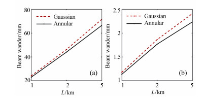
Figure 3. Beam wanders of the Gaussian beam and the annular beam in (a)uplink, (b)downlink

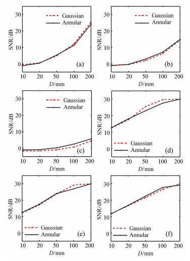
Figure 4. Scintillation index versus receiver aperture diameter D for (a)1 km uplink, (b)2 km uplink, (c)5 km uplink, (d)1 km downlink, (e)2 km downlink, (f)5 km downlink

Figure 5. Probability of fade versus receiver aperture diameter D for (a)1 km uplink, (b)2 km uplink, (c)5 km uplink, (d)1 km downlink, (e)2 km downlink, (f)5 km downlink
-
[1] MAKAVITA C D, JAYASINGHE S G, NGUYEN H D, et al.. Experimental study of command governor adaptive control for unmanned underwater vehicles[J]. IEEE Transactions on Control Systems Technology, 2019, 27(1):332-345. doi: 10.1109/TCST.2017.2757021 [2] SEDAGHATI S, ABDOLLAHI F, KHORASANI K. Model predictive and non-cooperative dynamic game fault recovery control strategies for a network of unmanned underwater vehicles[J]. International Journal of Control, 2017, doi: 10.1080/00207179.2017.1360517. [3] PREISIG J. Acoustic propagation considerations for underwater acoustic communications network development[C]. ACM International Workshop on Underwater Networks, ACM, 2006: 1-5. [4] CHITRE M, POTTER J, HENG O S. Underwater acoustic channel characterisation for medium-range shallow water communications[C]. Oceans '04. MTS/IEEE Techno-Ocean, IEEE, 2004: 40-45. [5] RATNI B, DE LUSTRAC A, PIAU G P, et al.. Reconfigurable meta-mirror for wavefronts control: applications to microwave antennas[J]. Optics Express, 2018, 26(3):2613-2624. doi: 10.1364/OE.26.002613 [6] ZHANG D, HAO SH Q, ZHAO Q S, et al.. Wavefront reconstruction method based on wavelet fractal interpolation for coherent free space optical communication[J]. Optics Communications, 2018, 410:723-729. doi: 10.1016/j.optcom.2017.11.021 [7] ELAMASSIE M, UYSAL M, BAYKAL Y, et al.. Effect of eddy diffusivity ratio on underwater optical scintillation index[J]. Journal of the Optical Society of America A, 2017, 34(11):1969-1973. doi: 10.1364/JOSAA.34.001969 [8] BORAH D K, VOELZ D G. Spatially partially coherent beam parameter optimization for free space optical communications[J]. Optics Express, 2010, 18(20):20746-20758. doi: 10.1364/OE.18.020746 [9] WANG M H, YUAN X H, MA D L. Potentials of radial partially coherent beams in free-space optical communication: a numerical investigation[J]. Applied Optics, 2017, 56(10):2851-2857. doi: 10.1364/AO.56.002851 [10] ZHU X M, KAHN J M. Free-space optical communication through atmospheric turbulence channels[J]. IEEE Transactions on Communications, 2002, 50(8):1293-1300. doi: 10.1109/TCOMM.2002.800829 [11] GERÇEKCIOǦLU H, BAYKAL Y, NAKIBOǦLU C. Annular beam scintillations in strong turbulence[J]. Journal of the Optical Society of America A, 2010, 27(8):1834-1839. doi: 10.1364/JOSAA.27.001834 [12] JI X L, CHEN H, JI G M. Characteristics of annular beams propagating through atmospheric turbulence along a downlink path and an uplink path[J]. Applied Physics B, 2016, 122(8):221. doi: 10.1007/s00340-016-6491-z [13] EYYUBOǦLU H T, ALTAY S, BAYKAL Y. Propagation characteristics of higher-order annular Gaussian beams in atmospheric turbulence[J]. Optics Communications, 2006, 264(1):25-34. doi: 10.1016/j.optcom.2006.02.030 [14] LI X Q, JI X L. Propagation characteristics of decentered annular beams through non-Kolmogorov turbulence[J]. Journal of the Optical Society of America A, 2014, 31(1):172-182. doi: 10.1364/JOSAA.31.000172 [15] CYWIAK M, CYWIAK D, YÁÑEZ E. Finite Gaussian wavelet superposition and Fresnel diffraction integral for calculating the propagation of truncated, non-diffracting and accelerating beams[J]. Optics Communications, 2017, 405:132-142. doi: 10.1016/j.optcom.2017.08.015 [16] FESHCHENKO R M, VINOGRADOV A V, ARTYUKOV I A. Propagation of waves from an arbitrary shaped surface-a generalization of the Fresnel diffraction integral[J]. Optics Communications, 2018, 413:291-294. doi: 10.1016/j.optcom.2017.12.070 [17] DWIVEDI G, SHARMA A, DEBNATH S, et al.. Comparison of numerical reconstruction of digital holograms using angular spectrum method and Fresnel diffraction method[J]. Journal of Optics, 2017, doi: 10.1007/s12596-017-0424-z. [18] CHEN SH G, ZHANG T L, HU L B, et al.. Vertical variations in optical properties of the waters in the Yellow Sea and Bohai Sea at seasonal scales and their influencing mechanisms[J]. Optics Express, 2018, 26(4):4112-4134. doi: 10.1364/OE.26.004112 [19] NIKISHOV V V, NIKISHOV V I. Spectrum of turbulent fluctuations of the sea-water refraction index[J]. International Journal of Fluid Mechanics Research, 2000, 27(1):82-98. doi: 10.1615/InterJFluidMechRes.v27.i1 [20] SCHMIDT J D. Numerical simulation of optical wave propagation with examples in MATLAB[J]. Proceedings of SPIE, 2010, PM199:212. https://www.researchgate.net/publication/303725548_Numerical_simulation_of_optical_wave_propagation_With_examples_in_MATLAB [21] ANDREWS L C, PHILIPS R L. Laser Beam Propagation Through Random Media[M]. 2nd ed. Bellingham, WA:SPIE, 2005. -

 下载:
下载:


图(6)
计量
- 文章访问数: 2501
- HTML全文浏览量: 1049
- PDF下载量: 194
- 被引次数: 0
