


-
摘要:
为了产生轴向双焦点中空环形光斑,基于矢量衍射积分得出的环带半径公式,设计产生了呈环带分布的轴向双焦点的螺旋相位,并研究了这种螺旋相位在高数值孔径物镜聚焦区域的光斑特性。首先,给出了线偏振以及圆偏振的涡旋光束在高数值孔径物镜聚焦条件下的积分表达式。然后,利用此积分表达式数值模拟了线偏振光与圆偏振光在不同轴向偏移距离及螺旋拓扑荷值时的聚焦光场分布。最后,将轴向双焦点螺旋相位加载到纯相位空间光调制器上,分别对圆偏振光与线偏振光入射进行实验研究。线偏振光入射时,实验产生了拓扑荷为1且轴向距离为±10 μm、±15 μm的双聚焦环形光斑;圆偏振光入射时,产生了轴向距离为±20 μm且拓扑荷为1到4时的双聚焦环形光斑。数值模拟与实验结果表明:圆偏振光与线偏振光经此螺旋相位调制后,在紧聚焦区域可产生轴向距离与暗斑大小可调的中空环形双焦点;圆偏振光较线偏振光产生的空心光斑光强分布更均匀,呈圆对称分布。此轴向双焦点螺旋相位有望在光学微操控、双光束超分辨纳米光刻以及STED显微成像方面获得一定的应用。
Abstract:In order to generate double doughnut-shaped focal spots at adjustable positions along the axial direction, a vortex phase zone plate based on a formula of annular radius derived from vector diffraction integral was designed. The focusing properties of the modulated vortex phase zone plate were further investigated in a tightly focused system. First, integral formulas of linearly and circularly polarized vortex beams were calculated under high NA focusing conditions. Then, the intensity distributions of linearly and circularly polarized vortex beams in a high NA focusing system were simulated by integral formulas with various axial shifting distances and topological charges. Finally, the corresponding experimental results of linearly and circularly polarized light were also given, utilizing a spatial light modulator loaded on double doughnut-shaped phase patterns. The double doughnut-shaped focal spots with a topological charge of 1 and axial distances of ±10 μm and ±15 μm were produced when the incident light was linearly polarized. As well as the double doughnut-shaped focal spots with axial distances of ±20 μm, topological charges of 1−4 were also produced when the incident light was circularly polarized. The simulated and experimental results demonstrated that two doughnut-shape focal spots with controllable axial shifting distances and dark spot sizes could be produced in the tight focusing region of a high NA objective when it is modulated by the vortex phase zone plate. This kind of vortex phase zone plate could be applied in the field of optical micromanipulation, two-beam super-resolution nanolithography, and Stimulated-Emission-Depletion (STED) fluorescence microscopy.
-
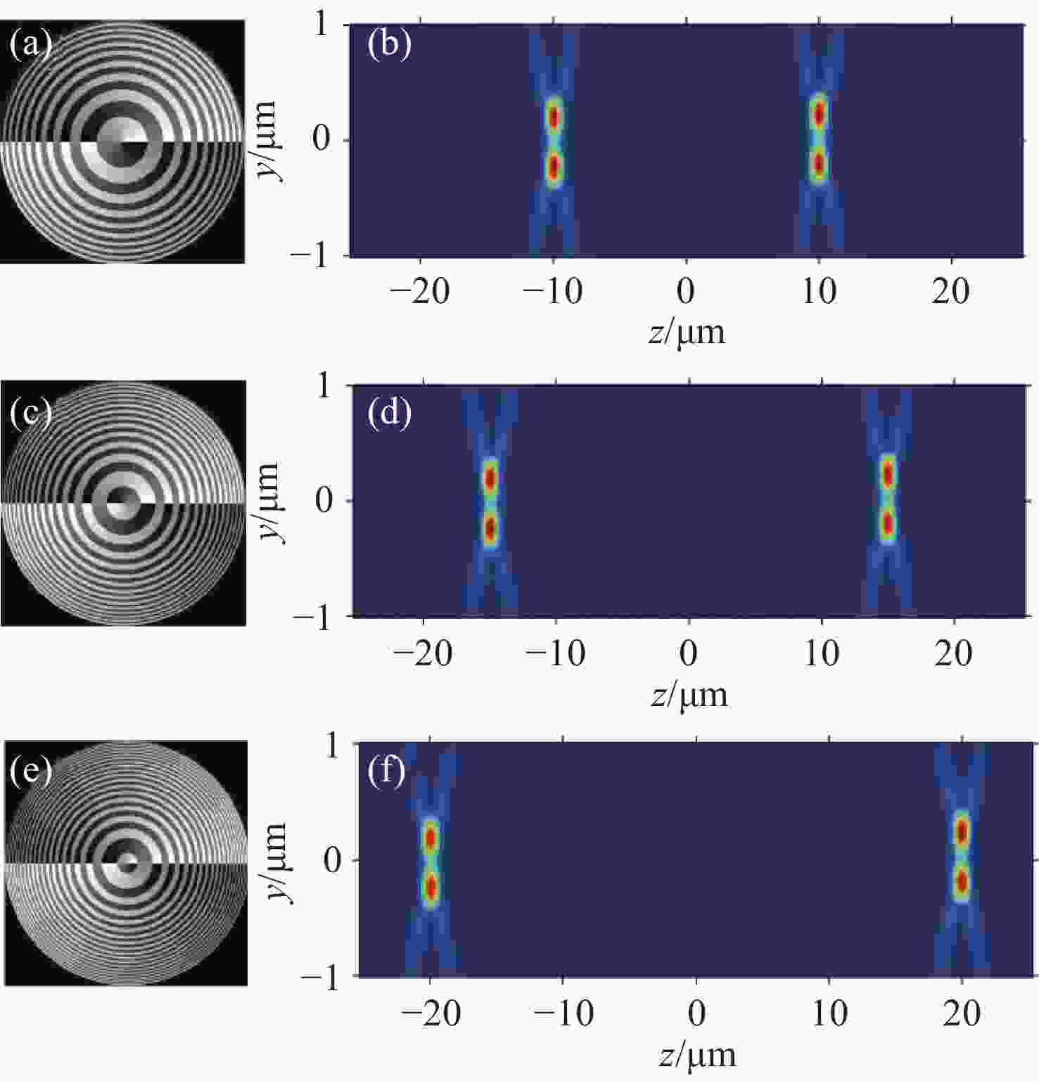
图 2 线偏振光入射时的数值模拟结果,其中拓扑荷n=1,数值孔径NA=0.85。涡旋相位图中的轴向偏移距离分布为:(a) |Δz|=10 μm,(c) |Δz|=15 μm,(e) |Δz|=20 μm。(b)、 (d)、 (f)分别为对应的yz截面光强分布图
Figure 2. The simulation results of incident linearly polarized light with n=1 and NA=0.85. The axial shift distances of the vortex phase zone plate are: (a) |Δz|=10 μm; (c) |Δz|=15 μm; (e) |Δz| = 20 μm. (b), (d) and (f) are the corresponding yz cross-section distributions of the total intensity in (a), (b) and (c), respectively
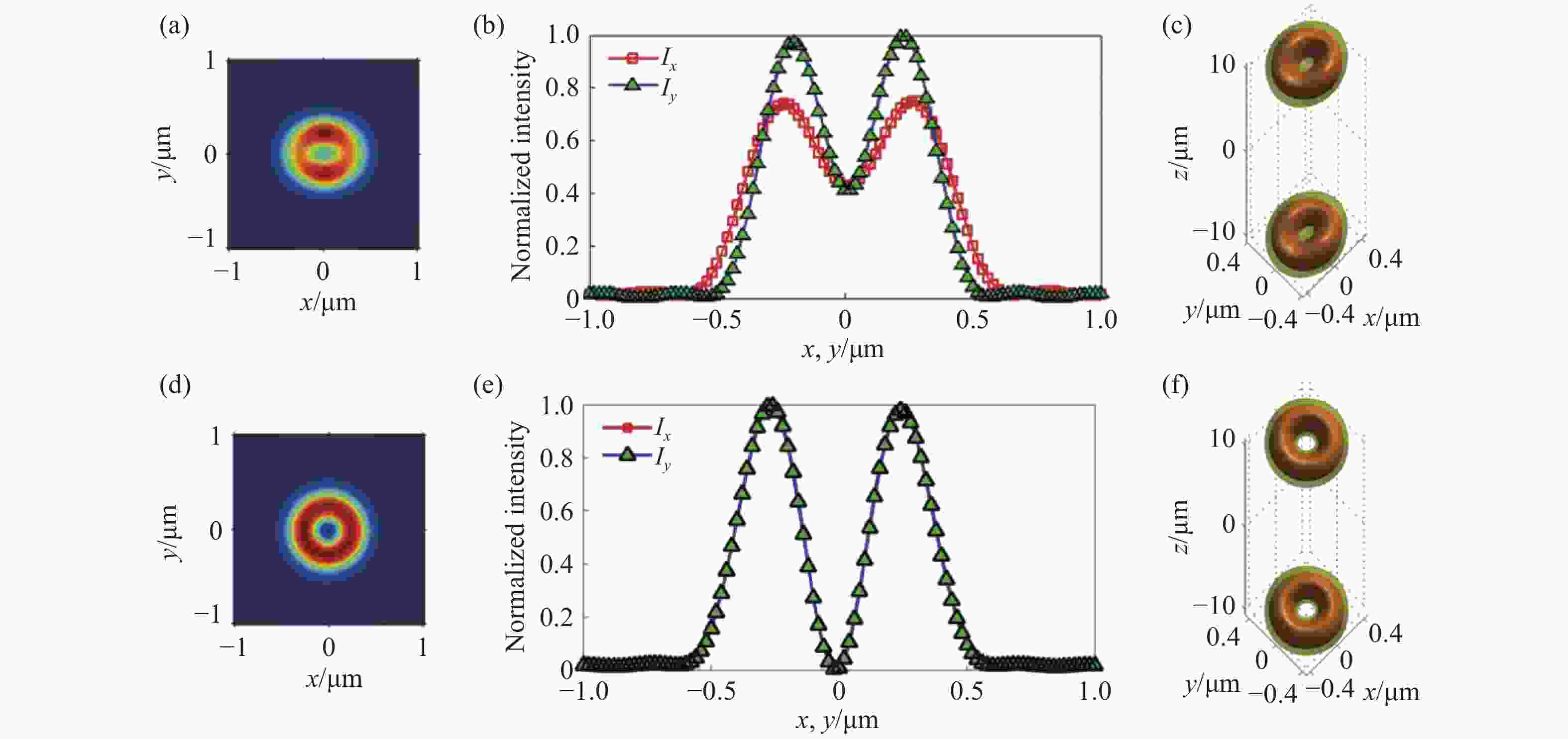
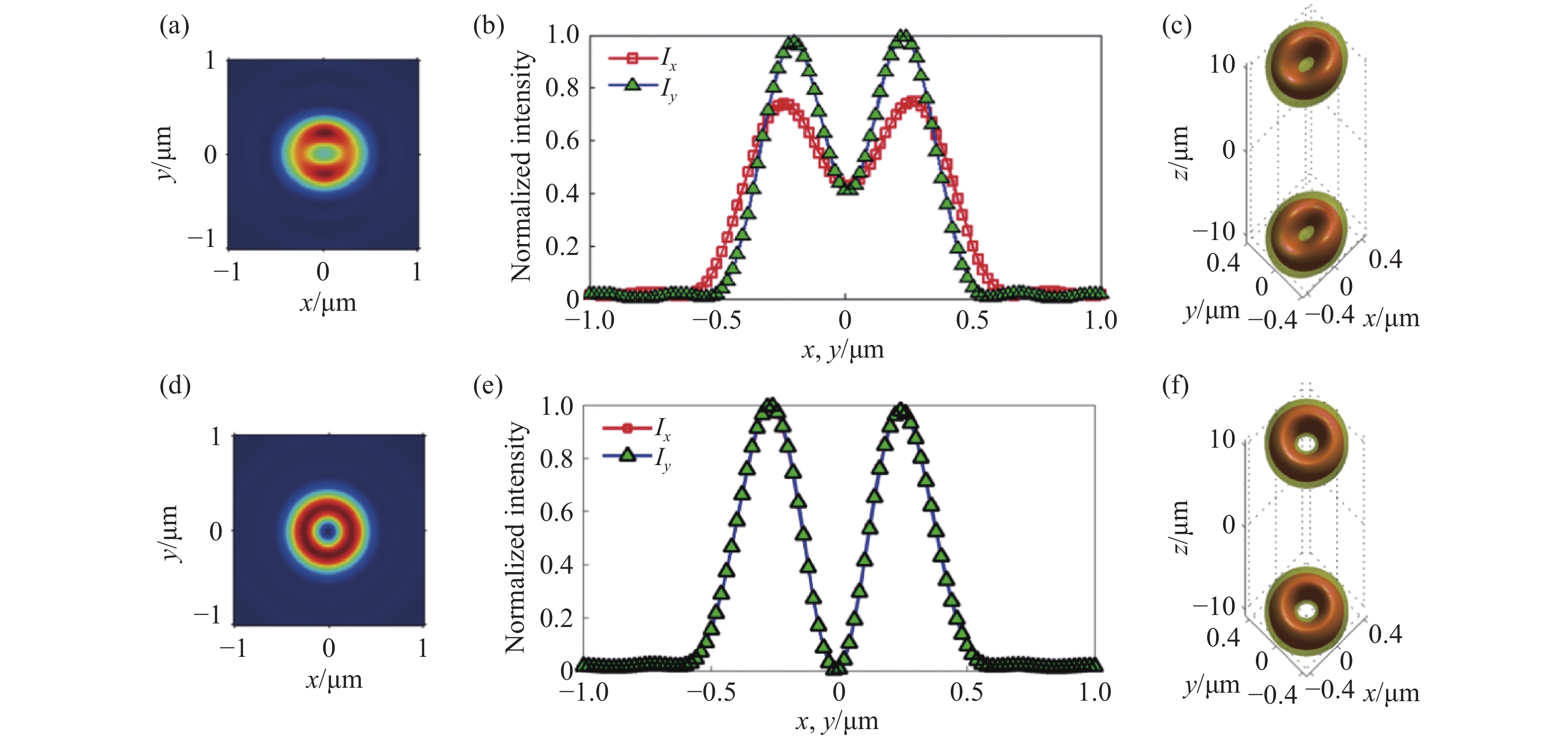
图 3 线偏振光 (a)~(c)和圆偏振光 (d)~(f)入射时的数值模拟结果,其中拓扑荷n = 1,轴向偏移距离|Δz|=10 μm,数值孔径NA=0.85。(a)、 (d)为聚焦光斑在xy截面上的光强分布; (b)、 (e)为聚焦光斑在一维x轴和y轴方向上的归一化光强分布; (c)、 (f)为聚焦场的三维强度等值面分布图,其中的等值面为I1 = 0.5Imax, I2 = 0.3Imax
Figure 3. The simulation results of linearly polarized light (a)−(c) and circularly polarized light (d)−(f) with n=1, |Δz|=10 μm and NA=0.85. (a), (d) are the xy cross-section distributions of total intensity; (b), (e) are the normalized intensity along x and y axis directions; (c), (f) are the 3D iso-surface plots of the total intensity with I1 = 0.5Imax, I2 = 0.3Imax
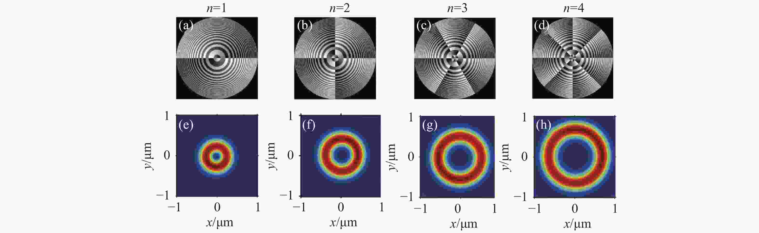
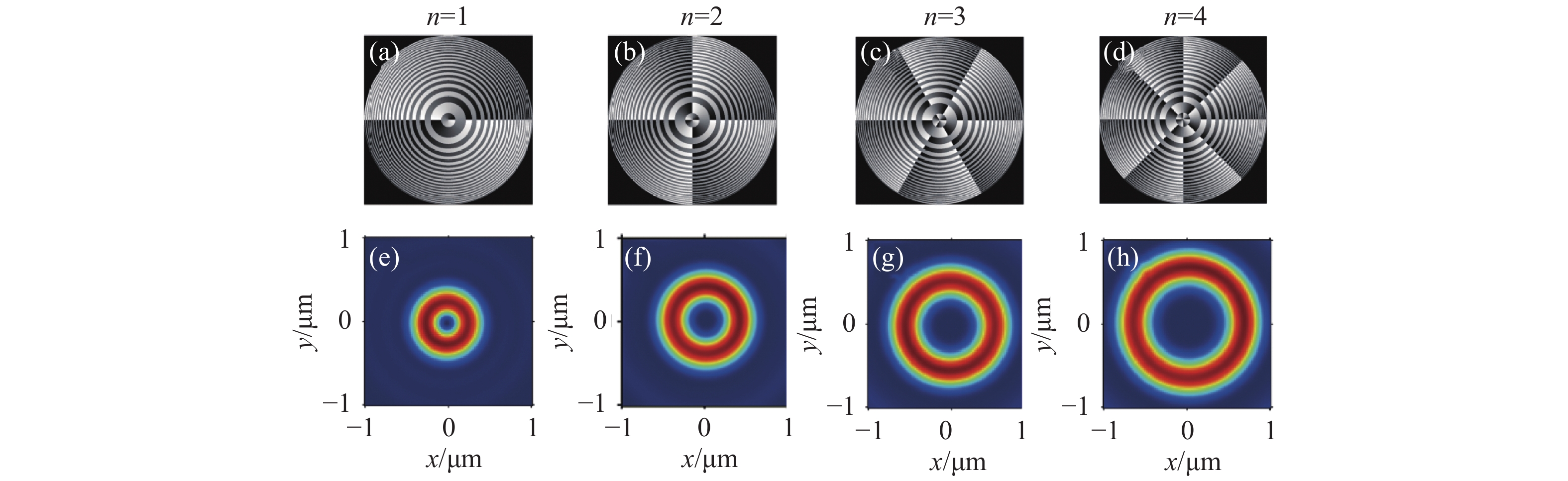
图 4 圆偏振光入射时的相位分布图 (a)~(d) 及其对应的紧聚焦xy截面的光场强度分布 (e)~(h)。其中,数值孔径NA=0.85,|Δz|=20 μm涡旋波带片的拓扑荷数: (a), (e) n=1;(b), (f) n=2;(c), (g) n=3;(d), (h) n=4
Figure 4. (a)−(d) are the phase distributions of vortex phase zone plate, (e)−(h) are the corresponding xy cross-section distributions of light intensity in the tight focusing field illuminated by circularly polarized light, in which NA=0.85, |Δz|=20 μm and the topology charge: (a), (e) n=1; (b), (f) n=2; (c), (g) n=3; (d), (h) n=4
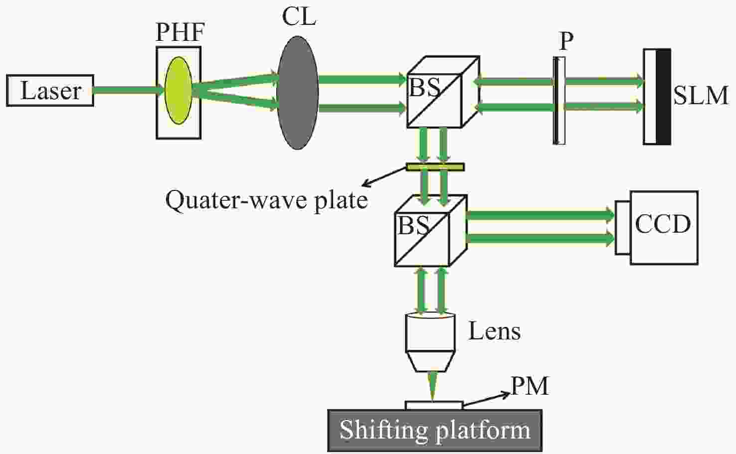
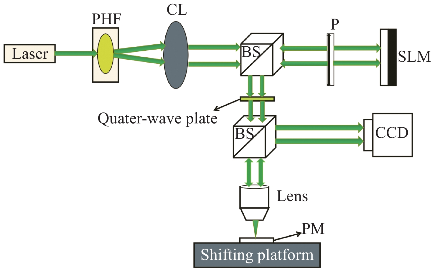
图 5 实验光路示意图。其中:PHF为针孔滤波器;CL为准直镜;BS为分束棱镜;P为偏振片;SLM为空间光调制器;PM为平面反射镜
Figure 5. Schematic diagram of the optical path in experiment, where PHF is a pin hole filter, CL is a collimation lens, BS is a beam splitter, P is a polarizer, SLM is a spatial light modulator, PM is a plane mirror

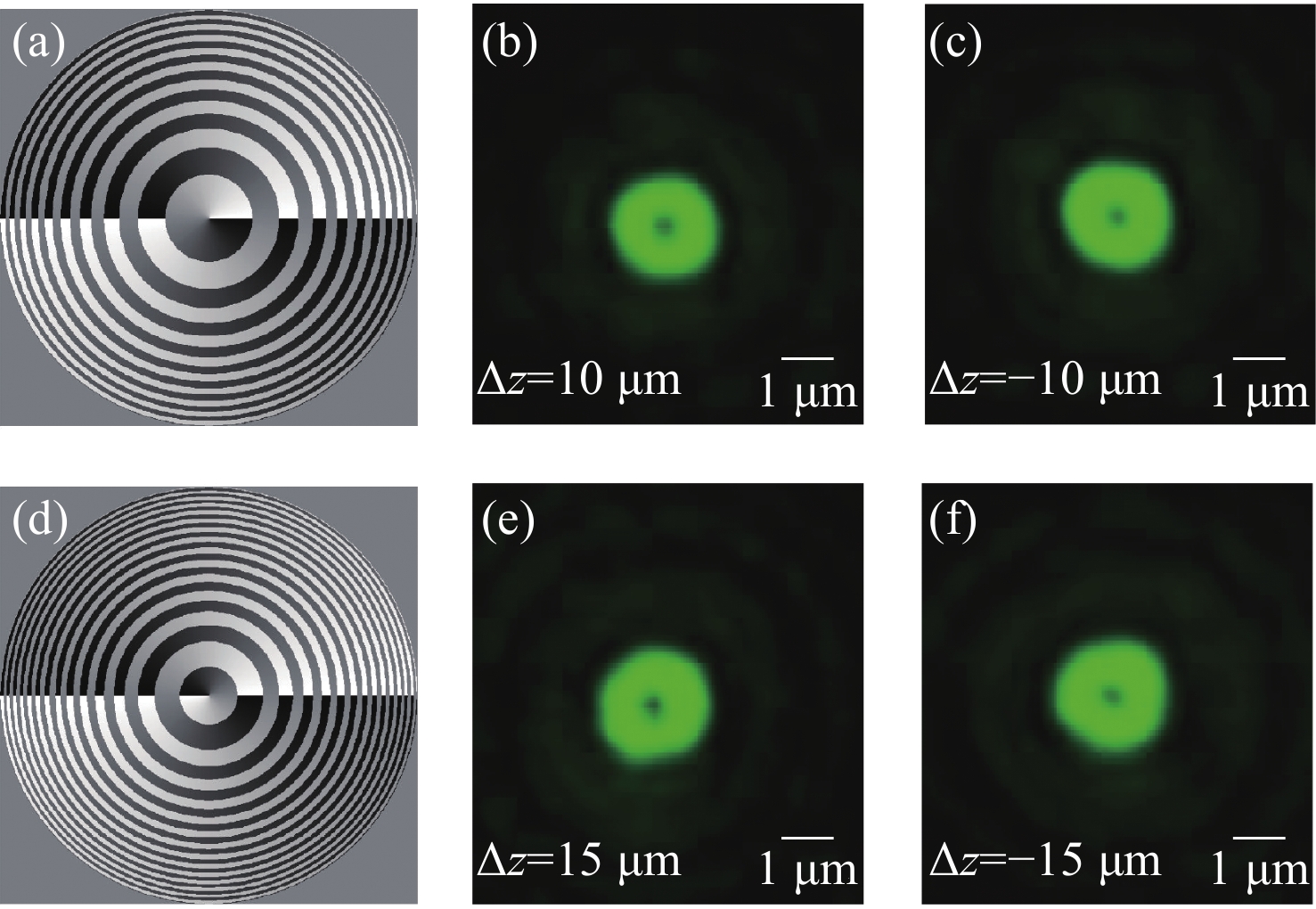
图 6 不同轴向距离的实验结果图。(a)、 (d)分别为轴向偏移|Δz|=10 μm和|Δz|=15 μm时的涡旋相位波带片的相位分布图; (b)、 (c)分别是±10 μm处xy截面的光场强度分布;图 (e)、 (f)分别是±15 μm处xy截面的光场强度分布图
Figure 6. The experimental results with different axial shift distances. (a), (d) are the vortex phase distributions with |Δz|=10 μm and |Δz|=15 μm; (b), (c) are the total intensity distributions on xy cross-section at 10 μm and −10 μm, respectively; (e), (f) are the total intensity distributions on xy cross-section at 15 μm and −15 μm, respectively
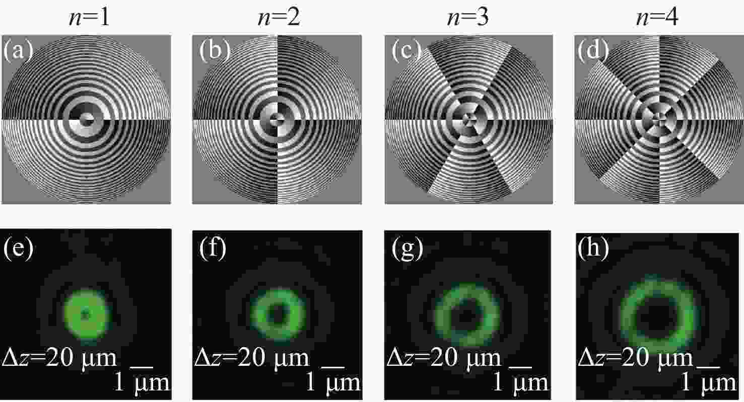
图 7 不同拓扑荷数xy截面光场分布实验图。图 (a)、 (b)、 (c)、 (d)分别为n=1、n=2、n=3和n=4时的波带片的相位分布图; (e)、 (f)、 (g)、 (h)分别为 (a)、 (b)、 (c)、 (d)对应波带片调制后的聚焦场在xy截面的光场分布
Figure 7. The experimental results of the focusing distribution on xy cross-section with different topology charges. (a), (b), (c), (d) are the phase distributions of the zone plate with n=1, n=2, n=3 and n=4, respectively; (e), (f), (g), (h) are the corresponding experimental results for (a), (b), (c) and (d) after zone plate modulation, respectively
-
[1] YOUNGWORTH K S, BROWN T G. Focusing of high numerical aperture cylindrical-vector beams[J]. Optics Express, 2000, 7(2): 77-87. doi: 10.1364/OE.7.000077 [2] 王思聪, 李向平. 紧聚焦轴对称矢量光场波前调控及应用[J]. 中国光学,2016,9(2):185-202. doi: 10.3788/co.20160902.0185WANG S C, LI X P. Wavefront manipulation of tightly focused cylindrical vector beams and its applications[J]. Chinese Optics, 2016, 9(2): 185-202. (in Chinese) doi: 10.3788/co.20160902.0185 [3] ZHOU ZH H, TAN Q F, JIN G F. Multiple 3D optical trapping using higher polarization order axially-symmetric polarized beams[J]. Chinese Optics, 2010, 3(1): 52-56. [4] GAN Z S, CAO Y Y, EVANS R A, et al. Three-dimensional deep sub-diffraction optical beam lithography with 9 nm feature size[J]. Nature Communications, 2013, 4: 2061. doi: 10.1038/ncomms3061 [5] HELL S W, WICHMANN J. Breaking the diffraction resolution limit by stimulated emission: stimulated-emission-depletion fluorescence microscopy[J]. Optics Letters, 1994, 19(11): 780-782. doi: 10.1364/OL.19.000780 [6] KOTLYAR V V, ALMAZOV A A, KHONINA S N, et al. Generation of phase singularity through diffracting a plane or Gaussian beam by a spiral phase plate[J]. Journal of the Optical Society of America A, 2005, 22(5): 849-861. doi: 10.1364/JOSAA.22.000849 [7] KHONINA S N, USTINOV A V, LOGACHEV V I, et al. Properties of vortex light fields generated by generalized spiral phase plates[J]. Physical Review A, 2020, 101(4): 043829. doi: 10.1103/PhysRevA.101.043829 [8] KHONINA S N, PODLIPNOV V V, KARPEEV S V, et al. Spectral control of the orbital angular momentum of a laser beam based on 3D properties of spiral phase plates fabricated for an infrared wavelength[J]. Optics Express, 2020, 28(12): 18407-18417. doi: 10.1364/OE.396199 [9] 高伟建, 王文宝, 朱士群. 利用位错光栅实现中空光束[J]. 光学学报,1998,18(10):1467-1469. doi: 10.3321/j.issn:0253-2239.1998.10.039GAO W J, WANG W B, ZHU SH Q. Obtaining hollow beam using dislocation grating[J]. Acta Optica Sinica, 1998, 18(10): 1467-1469. (in Chinese) doi: 10.3321/j.issn:0253-2239.1998.10.039 [10] 张淑芬, 姜珊, 董磊, 等. 基于衍射光栅的高精度干涉星敏感器的理论分析[J]. 中国光学,2021,14(6):1368-1377. doi: 10.37188/CO.2021-0051ZHANG SH F, JIANG SH, DONG L, et al. High accuracy interferometric star tracker based on diffraction grating[J]. Chinese Optics, 2021, 14(6): 1368-1377. (in Chinese) doi: 10.37188/CO.2021-0051 [11] 谭志华, 翁晓羽, 隋国荣, 等. 基于双环形旋涡相位调制的多焦点产生[J]. 光学仪器,2013,35(5):46-50. doi: 10.3969/j.issn.1005-5630.2013.05.011TAN ZH H, WENG X Y, SUI G R, et al. Multi-focal spots formed by the modulation of double ring-shape vortex phase plate[J]. Optical Instruments, 2013, 35(5): 46-50. (in Chinese) doi: 10.3969/j.issn.1005-5630.2013.05.011 [12] 蔡志华, 王孝坤, 胡海翔, 等. 计算全息法标定单光楔补偿检测系统误差[J]. 中国光学,2022,15(1):90-100. doi: 10.37188/CO.EN.2021-0004CAI ZH H, WANG X K, HU H X, et al. Calibration of single optical wedge compensation test system error by computer generation hologram[J]. Chinese Optics, 2022, 15(1): 90-100. (in Chinese) doi: 10.37188/CO.EN.2021-0004 [13] HAN J, INTARAVANNE Y, MA A N, et al. Optical metasurfaces for generation and superposition of optical ring vortex beams[J]. Laser &Photonics Reviews, 2020, 14(9): 2000146. [14] 李昊, 胡德骄, 秦飞, 等. 原子层厚度超表面光场调控原理及应用[J]. 中国光学,2021,14(4):851-866. doi: 10.37188/CO.2021-0069LI H, HU D J, QIN F, et al. Principle and application of metasurface optical field modulation of atomic layer thickness[J]. Chinese Optics, 2021, 14(4): 851-866. (in Chinese) doi: 10.37188/CO.2021-0069 [15] YU J J, ZHOU CH H, JIA W, et al. Circular Dammann grating under high numerical aperture focusing[J]. Applied Optics, 2012, 51(7): 994-999. doi: 10.1364/AO.51.000994 [16] YU J J, ZHOU CH H, JIA W, et al. Generation of tightly focused twin Bessel beams using circular Dammann gratings under radial polarization incidence[J]. Optics Communications, 2012, 285(21-22): 4166-4170. doi: 10.1016/j.optcom.2012.06.079 [17] XU L Q, WANG C W, QI X B, et al. Femtosecond laser direct writing continuous phase vortex gratings with proportionally distributed diffraction energy[J]. Applied Physics Letters, 2021, 119(13): 131101. doi: 10.1063/5.0061590 [18] YU J J, ZHOU CH H, JIA W, et al. Generation of dipole vortex array using spiral Dammann zone plates[J]. Applied Optics, 2012, 51(28): 6799-6804. doi: 10.1364/AO.51.006799 [19] YU J J, ZHOU CH H, JIA W, et al. Three-dimensional Dammann vortex array with tunable topological charge[J]. Applied Optics, 2012, 51(13): 2485-2490. doi: 10.1364/AO.51.002485 [20] LI M Y, LI W L, LI H Y, et al. Controllable design of super-oscillatory lenses with multiple sub-diffraction-limit foci[J]. Scientific Reports, 2017, 7(1): 1335. doi: 10.1038/s41598-017-01492-y [21] WU ZH X, DENG H, LI X X, et al. Generation of subdiffraction longitudinal bifoci by shaping a radially polarized wave[J]. Applied Optics, 2020, 59(26): 7841-7845. doi: 10.1364/AO.397584 [22] BADLOE T, KIM I, KIM Y, et al. Electrically tunable bifocal Metalens with diffraction-limited focusing and imaging at visible wavelengths[J]. Advanced Science, 2021, 8(21): 2102646. doi: 10.1002/advs.202102646 [23] SABATYAN A, EBRAHIMI H. Modified photon sieve as a high-performance bifocal and trifocal diffractive optical element[J]. Journal of the Optical Society of America A, 2018, 35(10): 1692-1700. doi: 10.1364/JOSAA.35.001692 [24] 冀胜哲, 朱林伟, 孙美玉, 等. 紧聚焦条件下的轴向双焦点波带片[J]. 光学学报,2015,35(3):0305003. doi: 10.3788/AOS201535.0305003JI SH ZH, ZHU L W, SUN M Y, et al. Axial two focus zone plate under tight foucsing conditions[J]. Acta Optica Sinica, 2015, 35(3): 0305003. (in Chinese) doi: 10.3788/AOS201535.0305003 [25] CHEN Y Y, LI J S, ZHANG H R, et al. Focusing and propagation properties of Bessel–Gaussian beam with a power-order mixing helical–conical phase wavefront[J]. Applied Optics, 2021, 60(4): 929-934. doi: 10.1364/AO.414356 [26] HUI Y F, CUI ZH W, LI Y X, et al. Propagation and dynamical characteristics of a Bessel–Gaussian beam in a chiral medium[J]. Journal of the Optical Society of America A, 2018, 35(8): 1299-1305. doi: 10.1364/JOSAA.35.001299 [27] 李晨昊, MAIER S A, 任浩然. 纳米光子学中的光学涡旋[J]. 中国光学,2021,14(4):792-811. doi: 10.37188/CO.2021-0066LI CH H, MAIER S A, REN H R. Optical vortices in nanophotonics[J]. Chinese Optics, 2021, 14(4): 792-811. (in Chinese) doi: 10.37188/CO.2021-0066 [28] DAI Y Y, ANTONELLO J, BOOTH M J. Calibration of a phase-only spatial light modulator for both phase and retardance modulation[J]. Optics Express, 2019, 27(13): 17912-17926. doi: 10.1364/OE.27.017912 [29] LI SH Q, XU X W, VEETIL R M, et al. Phase-only transmissive spatial light modulator based on tunable dielectric metasurface[J]. Science, 2019, 364(6445): 1087-1090. doi: 10.1126/science.aaw6747 [30] LIU Q, LIU T, YANG SH M, et al. Validation of vectorial theories for the focusing of high numerical aperture Fresnel zone plates[J]. Optics Communications, 2018, 429: 119-126. doi: 10.1016/j.optcom.2018.08.010 [31] ZHUANG J L, ZHANG L P, DENG D M. Tight-focusing properties of linearly polarized circular Airy Gaussian vortex beam[J]. Optics Letters, 2020, 45(2): 296-299. doi: 10.1364/OL.45.000296 [32] HU Y F, LIU X, JIN M K, et al. Dielectric metasurface zone plate for the generation of focusing vortex beams[J]. PhotoniX, 2021, 2(1): 10. doi: 10.1186/s43074-021-00035-z [33] CHEN L X. Quantum discord of thermal two-photon orbital angular momentum state: mimicking teleportation to transmit an image[J]. Light:Science &Applications, 2021, 10(1): 148. [34] 胡孔云, 肖光宗, 张莹, 等. 采用超连续谱激光的双光束光纤光阱实验[J]. 中国光学,2017,10(3):370-375. doi: 10.3788/co.20171003.0370HU K Y, XIAO G Z, ZHANG Y, et al. Double-beam fiber optical trap experiments based on supercontinuum laser[J]. Chinese Optics, 2017, 10(3): 370-375. (in Chinese) doi: 10.3788/co.20171003.0370 [35] 明昕宇, 国旗, 薛兆康, 等. 飞秒激光刻写低温度灵敏度的细芯长周期光栅[J]. 中国光学,2020,13(4):737-744. doi: 10.37188/CO.2020-0015MING X Y, GUO Q, XUE ZH K, et al. A femtosecond laser-inscribed fine-core long-period grating with low temperature sensitivity[J]. Chinese Optics, 2020, 13(4): 737-744. (in Chinese) doi: 10.37188/CO.2020-0015 [36] WANG S C, WEI CH, FENG Y H, et al. Dual-shot dynamics and ultimate frequency of all-optical magnetic recording on GdFeCo[J]. Light:Science &Applications, 2021, 10(1): 8. [37] RICHARDS B, WOLF E. Electromagnetic diffraction in optical systems, II. Structure of the image field in an aplanatic system[J]. Proceedings of the Royal Society A:Mathematical,Physical and Engineering Sciences, 1959, 253(1274): 358-379. [38] WOLF E. Electromagnetic diffraction in optical systems I. An integral representation of the image field[J]. Proceedings of the Royal Society A:Mathematical,Physical and Engineering Sciences, 1959, 253(1274): 349-357. [39] ZHAN Q W. Properties of circularly polarized vortex beams[J]. Optics Letters, 2006, 31(7): 867-869. doi: 10.1364/OL.31.000867 [40] 曹耀宇, 谢飞, 张鹏达, 等. 双光束超分辨激光直写纳米加工技术[J]. 光电工程,2017,44(12):1133-1145.CAO Y Y, XIE F, ZHANG P D, et al. Dual-beam super-resolution direct laser writing nanofabrication technology[J]. Opto-Electronic Engineering, 2017, 44(12): 1133-1145. (in Chinese) [41] LI X P, CAO Y Y, TIAN N, et al. Multifocal optical nanoscopy for big data recording at 30 TB capacity and gigabits/second data rate[J]. Optica, 2015, 2(6): 567-570. doi: 10.1364/OPTICA.2.000567 [42] ZHU L W, CAO Y Y, CHEN Q Q, et al. Near-perfect fidelity polarization-encoded multilayer optical data storage based on aligned gold nanorods[J]. Opto-Electronic Advances, 2021, 4(11): 210002. doi: 10.29026/oea.2021.210002 [43] GAO Y F, XIA X Y, LIU L N, et al. Axial gradient excitation accelerates volumetric imaging of two-photon microscopy[J]. Photonics Research, 2022, 10(3): 687-696. doi: 10.1364/PRJ.441778 [44] COMSTOCK M J, WHITLEY K D, JIA H F, et al. Direct observation of structure-function relationship in a nucleic acid-processing enzyme[J]. Science, 2015, 348(6232): 352-354. doi: 10.1126/science.aaa0130 [45] MUDRY E, LE MOAL E, FERRAND P, et al. Isotropic diffraction-limited focusing using a single objective lens[J]. Physical Review Letters, 2010, 105(20): 203903. doi: 10.1103/PhysRevLett.105.203903 -

 下载:
下载:


计量
- 文章访问数: 1436
- HTML全文浏览量: 667
- PDF下载量: 454
- 被引次数: 0
