


Microwave photonic RF frequency multiplying phase shifter with tunable multiplication factor and a full 360-deg tunable range
doi: 10.37188/CO.EN.2022-0019
-
摘要:
提出一种倍频因子连续可调,且相位连续变化的微波光子移相系统。该方案使用两个并联的马赫曾德尔调制器,通过2×2光耦器与两个双并联的集成马赫曾德尔调制器级联,产生可调节的±1~4阶边带,并使用相位调制器对其中一个光波进行相移。通过调整DPMZM的射频驱动信号和直流偏置电压以及PM的直流电压,可以产生相位从0到360°连续可调的2到8次谐波。仿真结果表明,当射频信号频率为10 GHz时,可产生频率为20~80 GHz的微波信号。当相位调制器的直流偏置电压与半波电压比值在0到2间变化时,对应微波信号的相位从0°到360°变化,可以获得约20 dB的大光边带抑制比(OSSR)和电杂散抑制比(ESSR)。此外,分析了调制器消光比对输出微波信号光载波抑制比和电杂散抑制比的影响,以及光载波的波长和功率对微波信号幅度波动的影响。
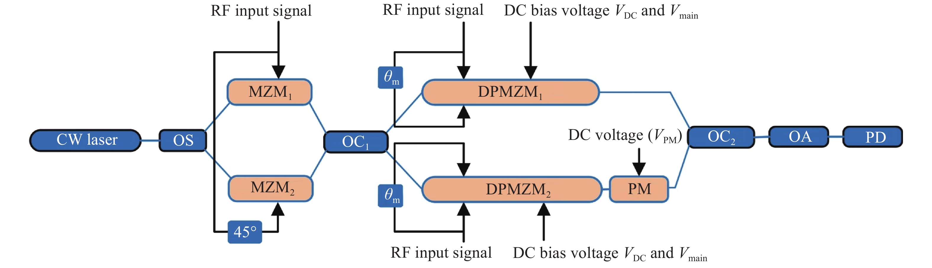
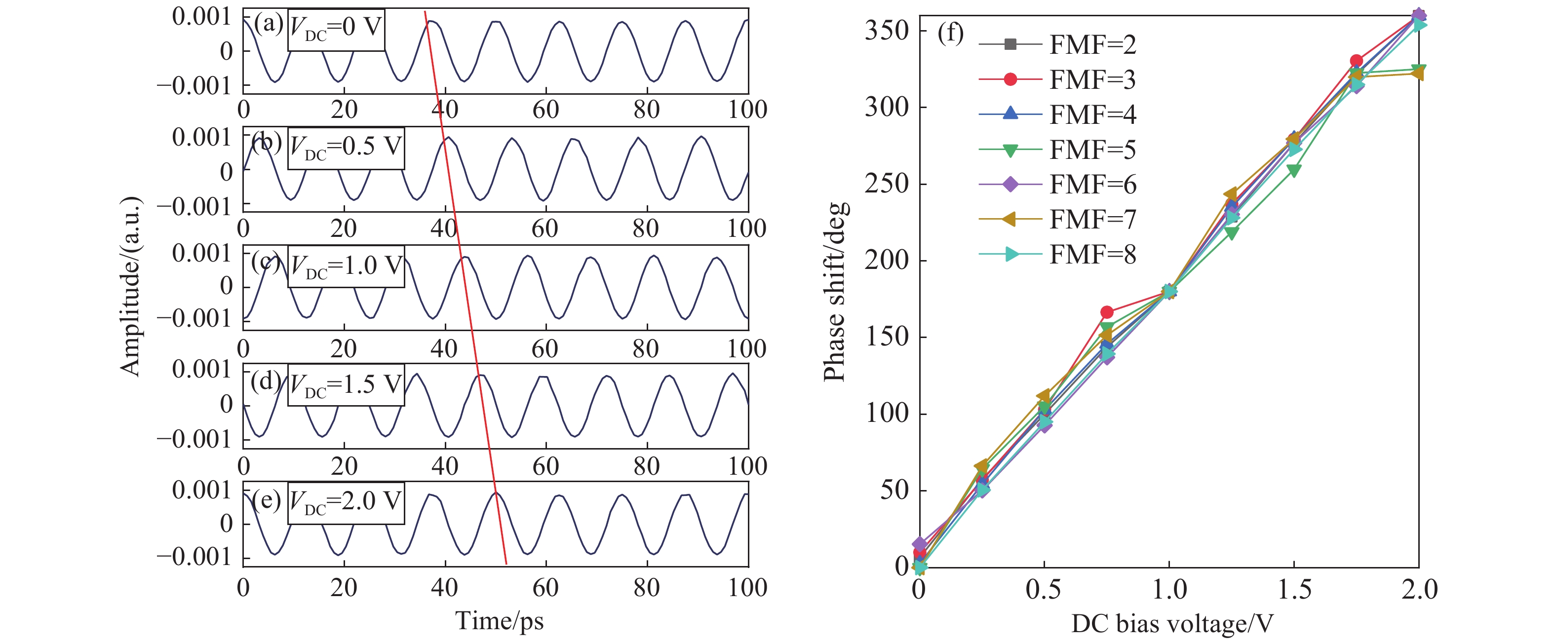
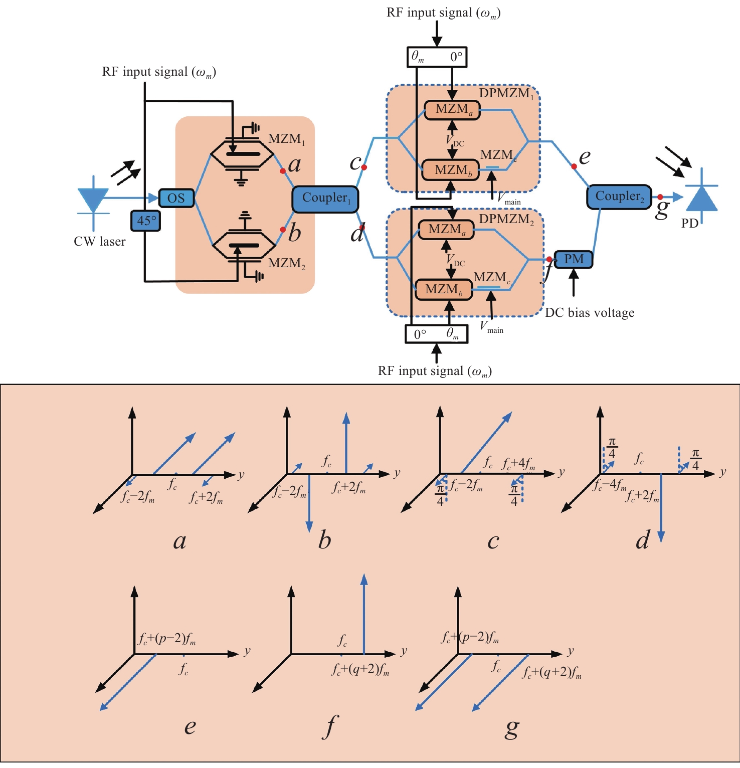
Abstract:A filterless Microwave Photonic Phase Shifter (MPPS) with a tunable Frequency Multiplication Factor (FMF) and a full 360-deg tunable range is theoretically analyzed and verified by simulation. In the scheme, two parallel Mach-Zehnder Modulators (MZM), cascaded with two Dual-Parallel integrated Mach-Zehnder Modulators (DPMZM) by a 2×2 Optical Coupler (OC), are used to generate the ±1st- to 4th-order sidebands adjustably, and a Phase Modulator (PM) is used to phase shift one of the two lightwaves. After photodetection, the 2nd- to 8th- order harmonics with a continuously tunable phase shift from 0 to 360-deg can be generated by adjusting the RF driving signal and the DC bias voltage of the DPMZM, and the DC voltage of the PM. Simulation results demonstrate that both 360-deg continuously tunable phase shift and frequency multiplication can be implemented. Large Optical Sideband Suppression Ratio (OSSR) and Electrical Spurious Suppression Ratio (ESSR) of around 20 dB can be obtained. The phase shifter wavelength insensitive performance has been also evaluated by simulation.
-
Key words:
- microwave photonics /
- phase shifter /
- frequency multiplication /
- Mach-Zehnder modulator
-
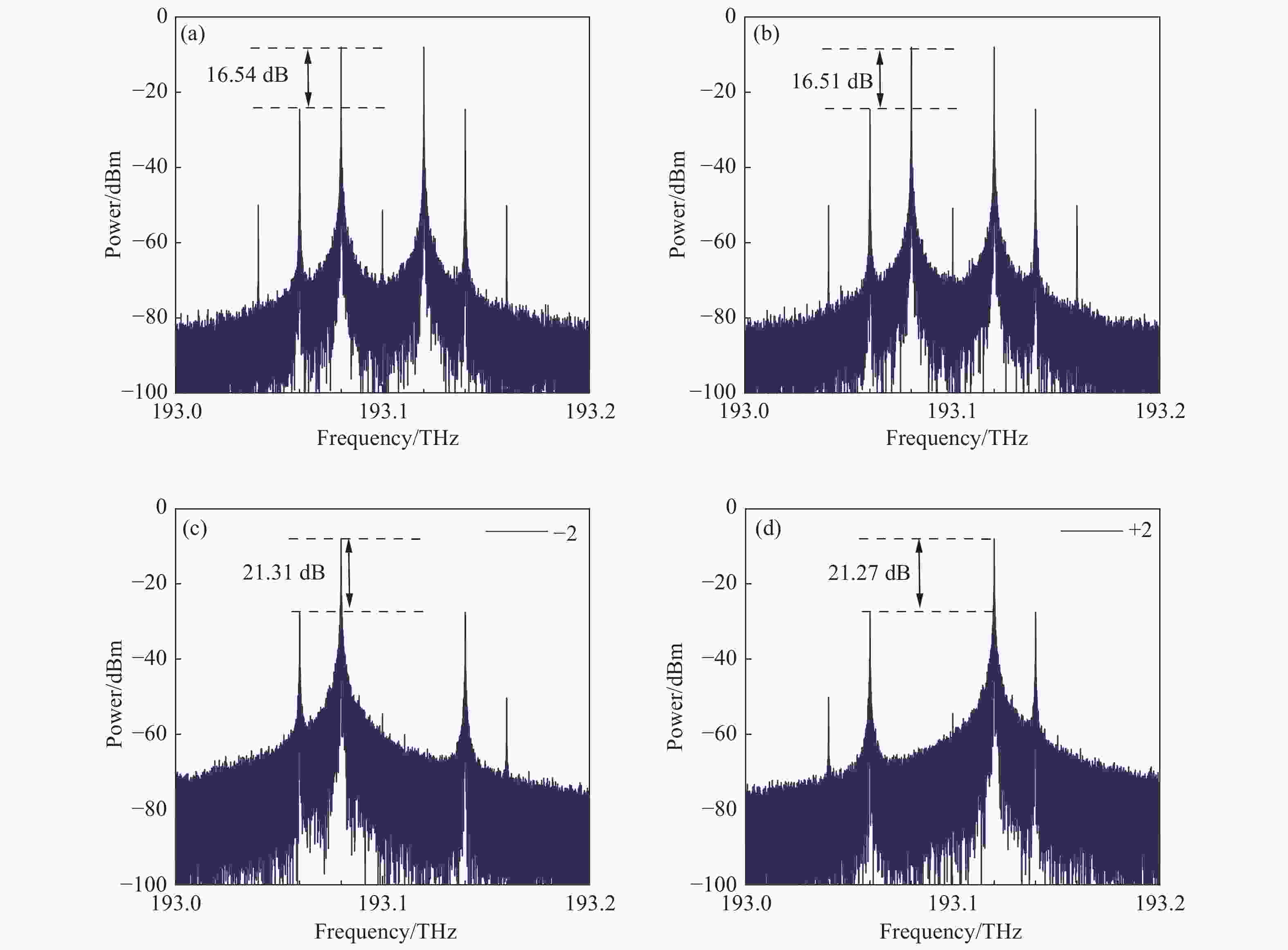
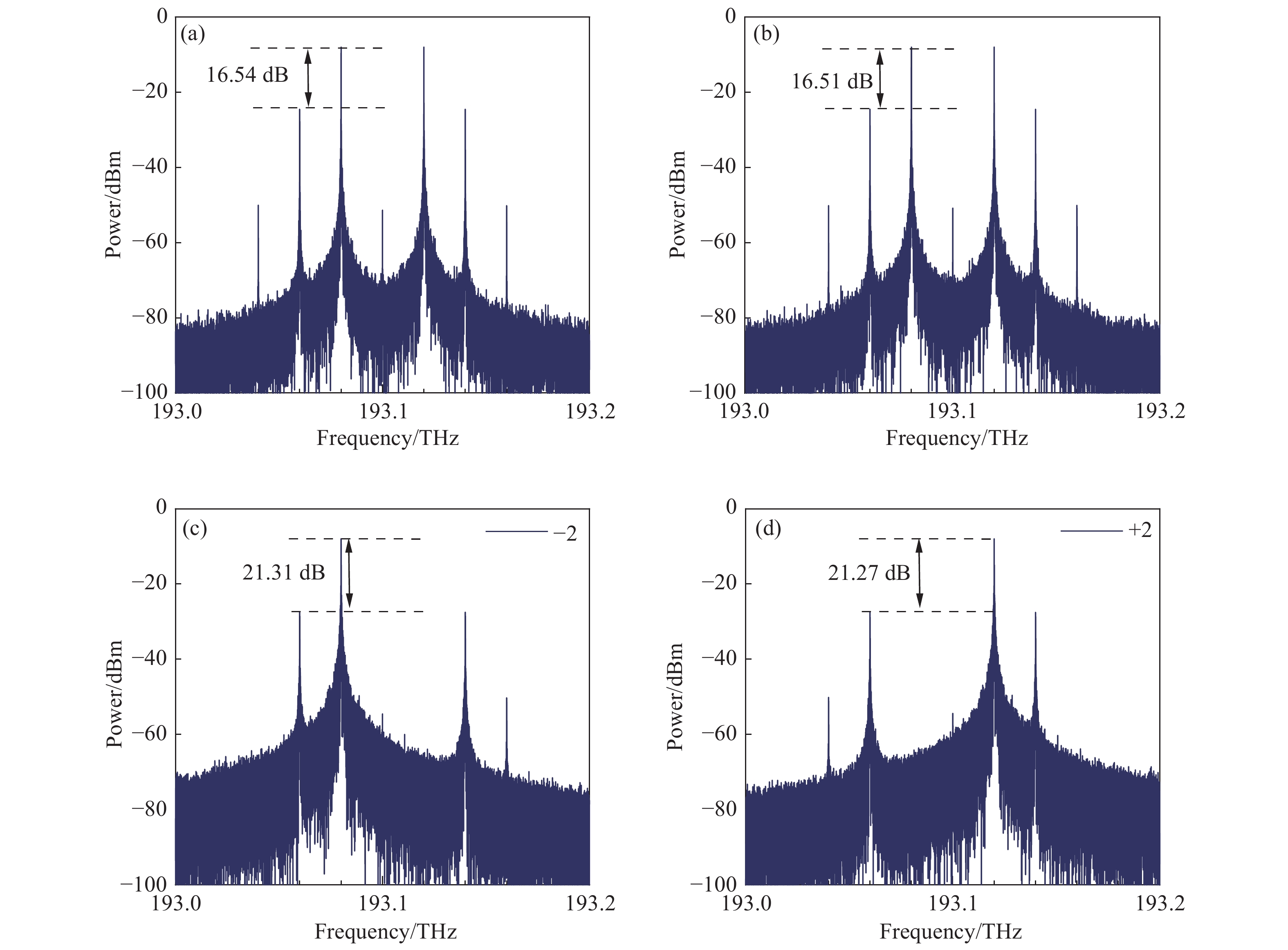
Figure 3. Optical spectra of the CS-DSB modulated signal from the MZM1(a) and MZM2(b) and CS-SSB modulated signal from the upper (c) and lower (d) port of the OC1
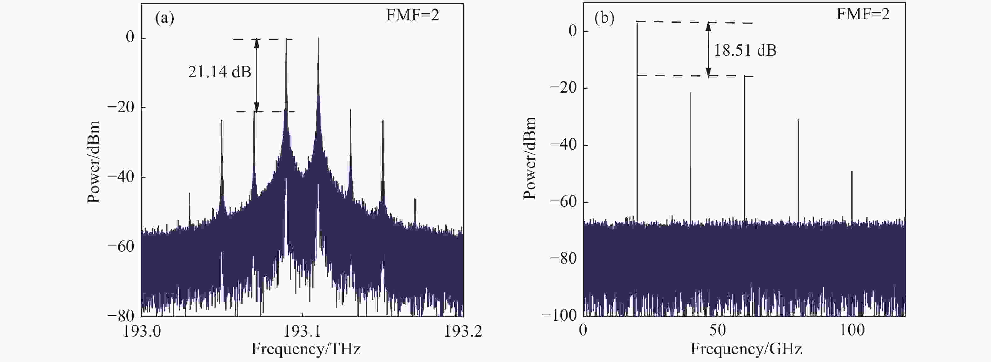
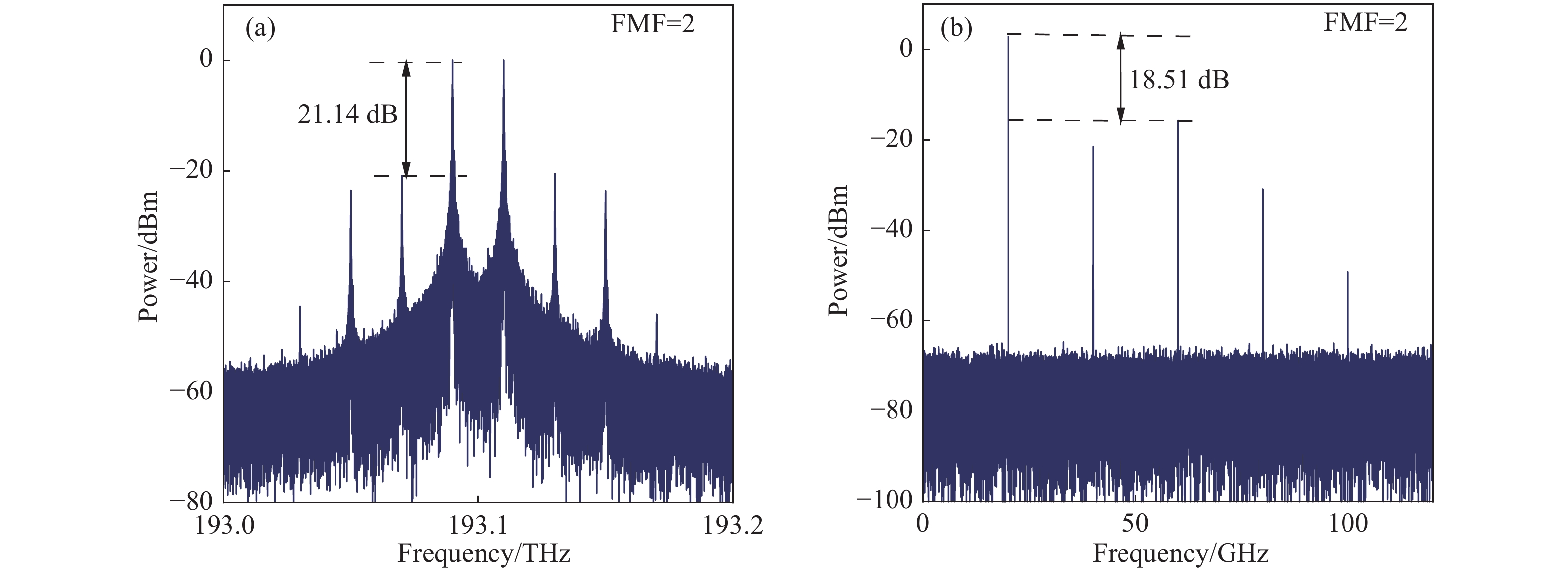
Figure 4. (a) Optical spectra of the output of the OC2 and (b) electrical spectra of the photocurrent output from the PD at FMF of 2
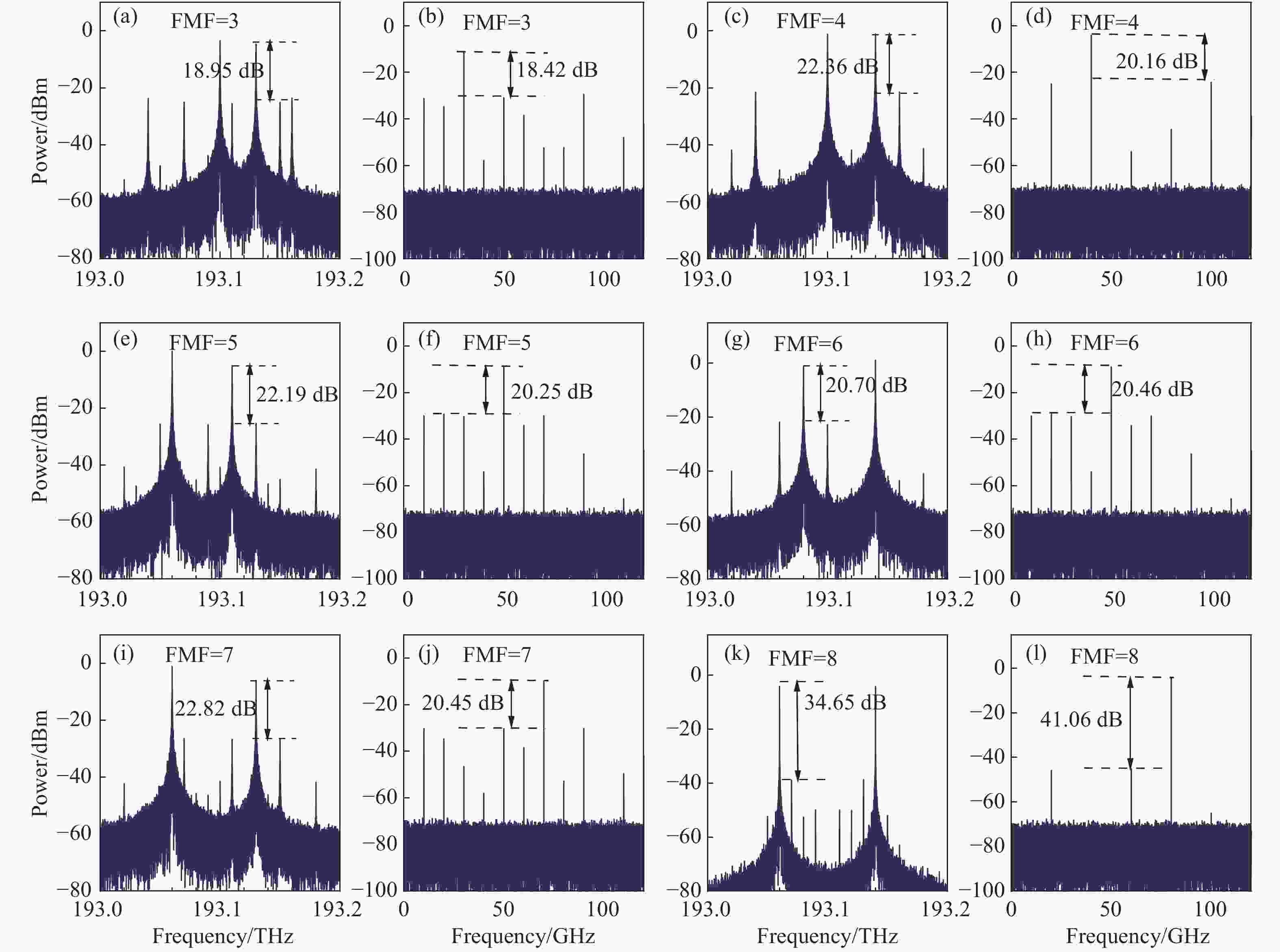
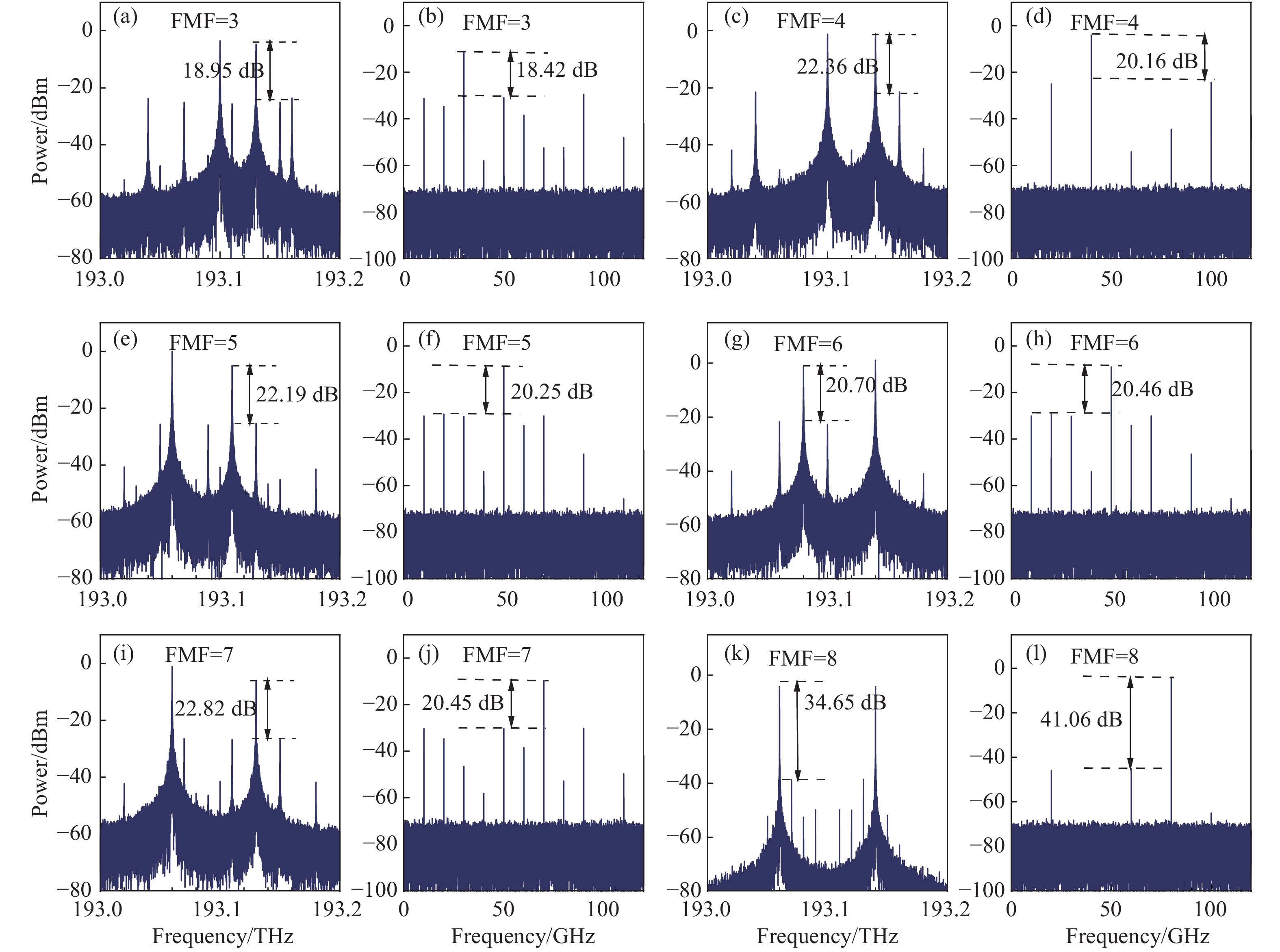
Figure 5. Optical spectra of the output of the OC2 and electric domain spectra with FMF at 3 (a)(b), 4(c)(d), 5 (e)(f), 6 (g)(h), 7 (i)(j) and 8 (k)(l), respectively
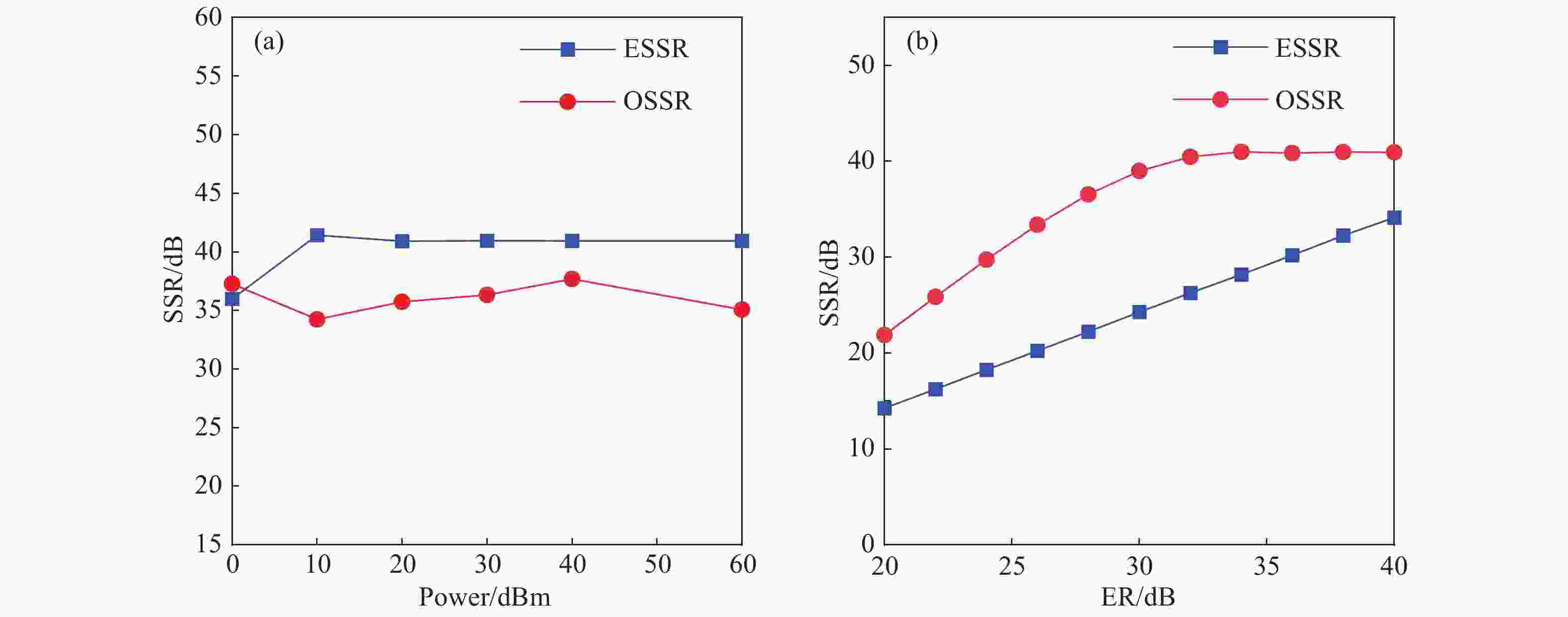
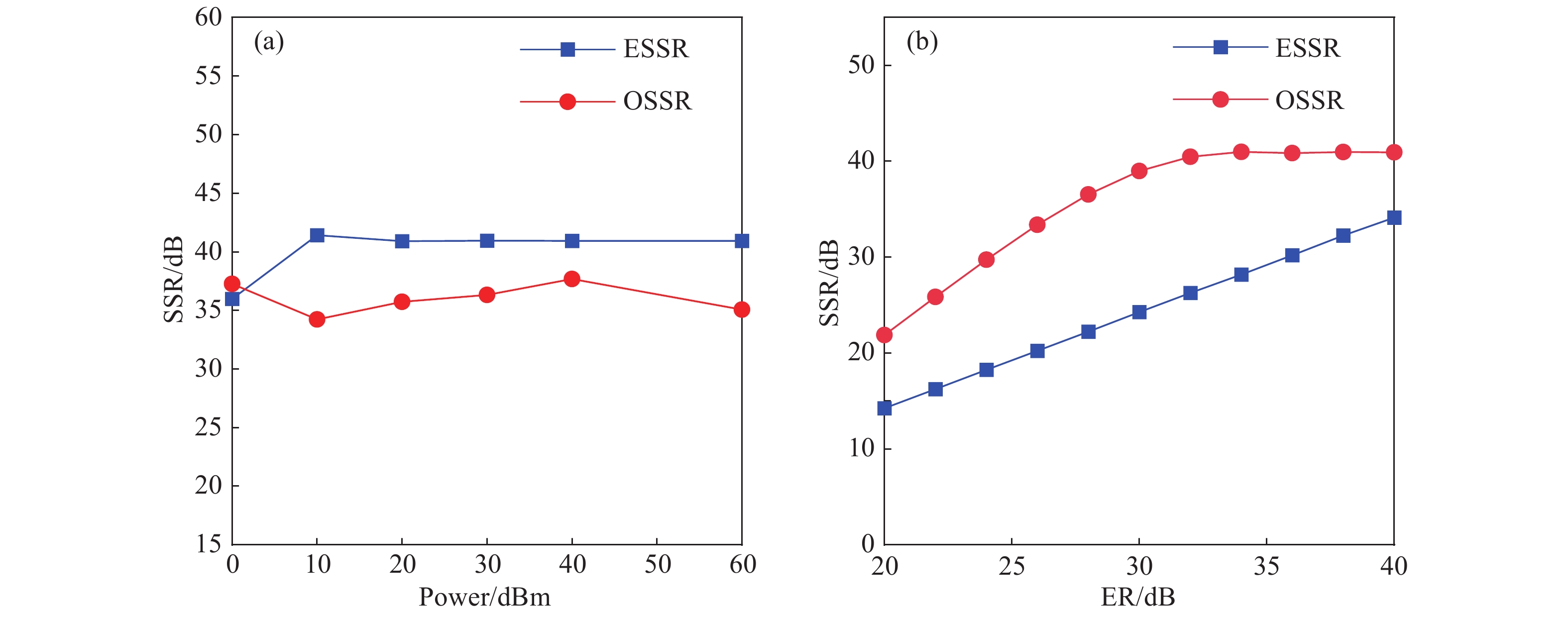
Figure 7. (a) OSSR and ESSR of the generated microwaves signal varying with power of CW laser and (b) varying with ERs of MZM1
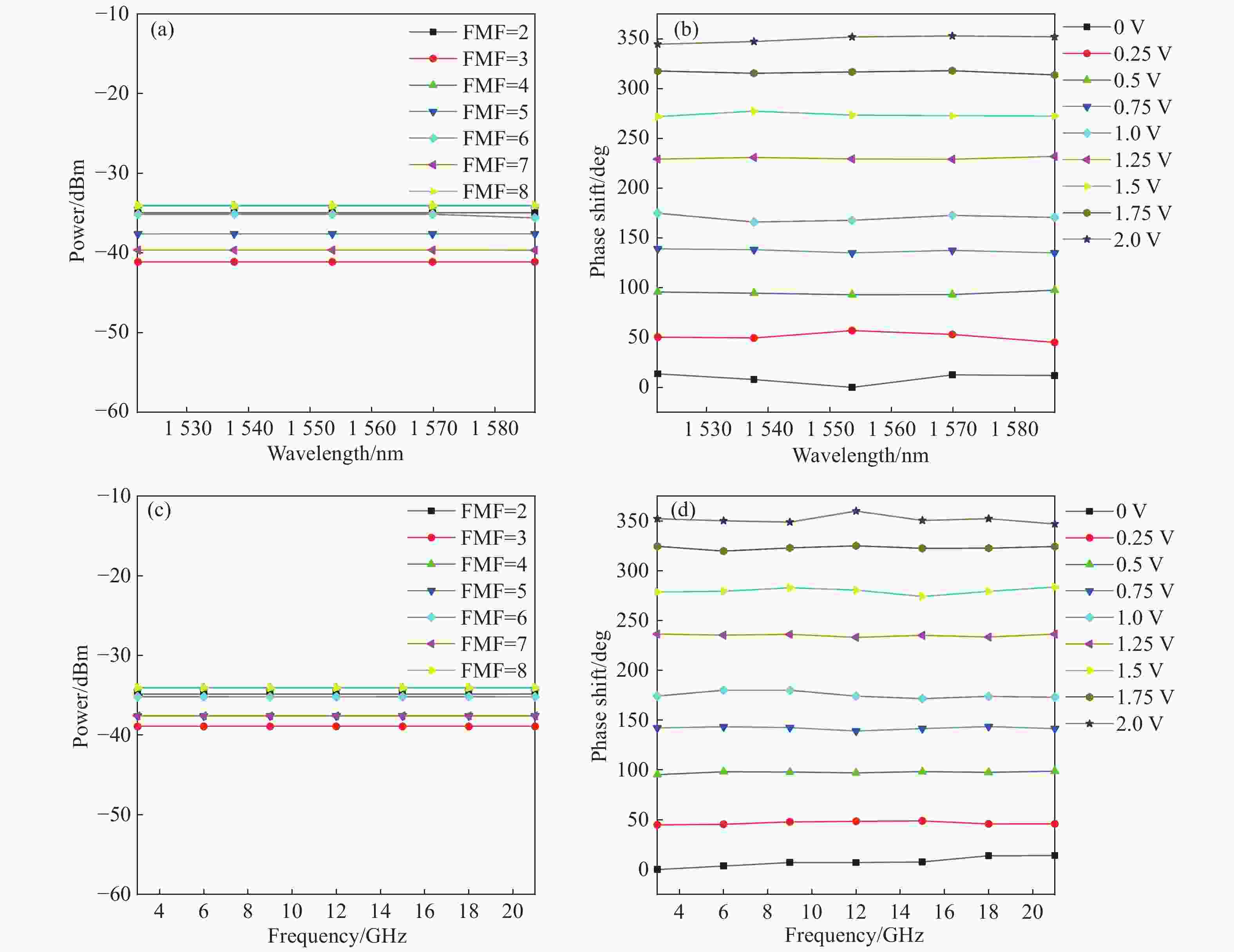
Figure 9. Measured power of the generated signal at different frequencies of the optical carrier (a) and RF driving signal (c), and phase response of the FMPS at different frequencies of the optical carrier (b) and RF driving signal (d) when FMF=8
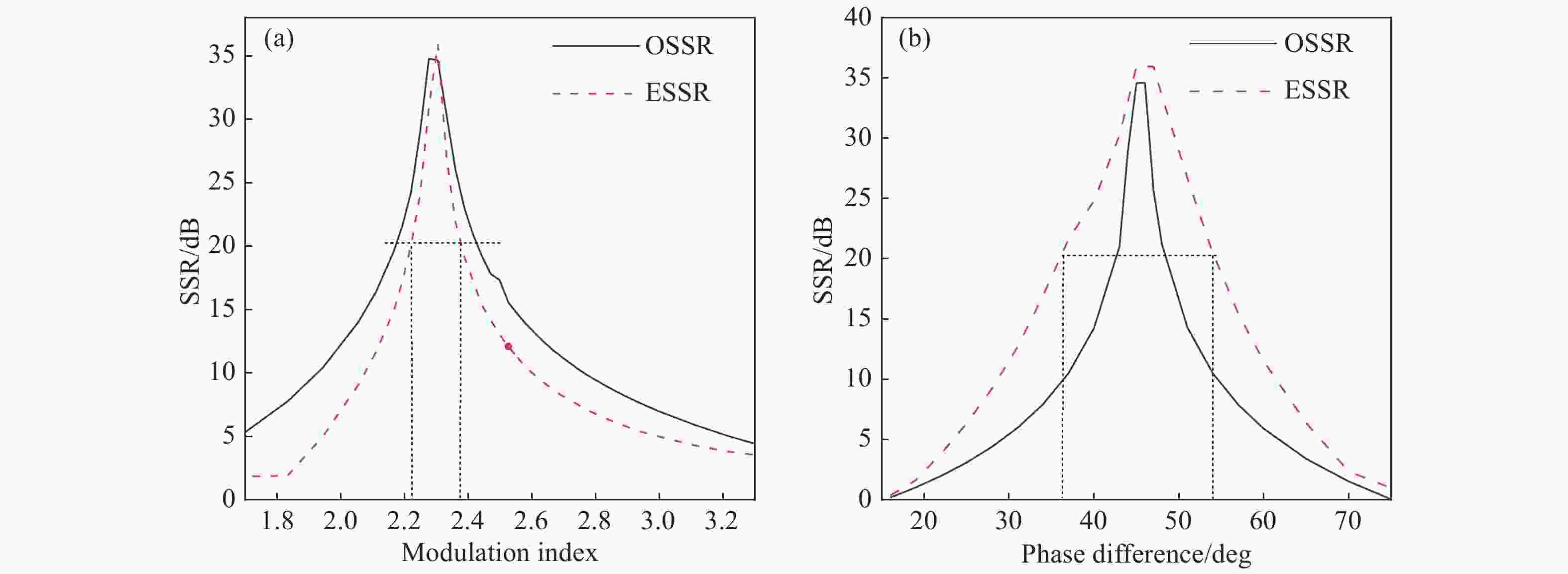
Figure 10. OSSR and ESSR of the generated microwave signal when (a) the modulation index of MZM1 is varied from 2.05 to 2.77 and (b) the phase difference between the two input RF signals changes from 16° to 75° when FMF=8
Table 2. Parameters of DPMZM1 and DPMZM2 setting table
FMF=4−p+q DPMZM1 DPMZM2 Order=p−2 θm VDC Vmain p Order=2+q θm VDC Vmain q 2 −1 π/2 Vπ −Vπ/2 +1 1 π/2 Vπ Vπ/2 −1 3 0 π/4 0 −Vπ/2 +2 3 π/2 Vπ −Vπ/2 +1 4 −1 π/2 Vπ −Vπ/2 +1 3 π/2 Vπ −Vπ/2 +1 5 −1 π/2 Vπ −Vπ/2 +1 4 π/4 0 −Vπ/2 +2 6 −3 π/2 Vπ Vπ/2 −1 3 π/2 Vπ −Vπ/2 +1 7 −3 π/2 Vπ Vπ/2 −1 4 π/4 0 −Vπ/2 +2 8 −4 π/4 0 Vπ/2 −2 4 π/4 0 −Vπ/2 +2  下载: 导出CSV
-
[1] SERAFINO G, PORZI C, HUSSAIN B, et al. High-performance beamforming network based on si-photonics phase shifters for wideband communications and radar applications[J]. IEEE Journal of Selected Topics in Quantum Electronics, 2020, 26(5): 6101011. [2] CHEN D, MA J X. Microwave photonic up- and down-converter with tunable phase shift based on an integrated dual-polarization dual-parallel Mach-Zehnder modulator without optically filtering[J]. Fiber and Integrated Optics, 2020, 39(2): 97-107. doi: 10.1080/01468030.2020.1734117 [3] GAO Y SH, WEN A J, TU ZH Y, et al. Simultaneously photonic frequency downconversion, multichannel phase shifting, and IQ demodulation for wideband microwave signals[J]. Optics Letters, 2016, 41(19): 4484-4487. doi: 10.1364/OL.41.004484 [4] CHEN Y. A wideband photonic microwave phase shifter with 360-degree phase tunable range based on a DP-QPSK modulator[J]. Optics Communications, 2018, 410: 787-792. doi: 10.1016/j.optcom.2017.11.041 [5] ZHANG Y M, PAN SH L. Broadband microwave signal processing enabled by polarization-based photonic microwave phase shifters[J]. IEEE Journal of Quantum Electronics, 2018, 54(4): 0700112. [6] LI H, ZHAO SH H, LIN T, et al. A filterless reconfigurable frequency mixer based on a wideband photonic microwave phase shifter[J]. Optics Communications, 2020, 475: 126224. doi: 10.1016/j.optcom.2020.126224 [7] LIN D D, XU X M, ZHENG P F, et al. A high-performance microwave photonic phase shifter based on cascaded silicon nitride microrings[J]. IEEE Photonics Technology Letters, 2020, 32(19): 1265-1268. doi: 10.1109/LPT.2020.3019798 [8] ZHANG Y M, LI ZH Y, CHEN W J, et al. Broadband image-reject mixing based on a polarization-modulated dual-channel photonic microwave phase shifter[J]. IEEE Photonics Journal, 2020, 12(2): 7800409. [9] CHEW S X, SONG SH J, LI L W, et al. Inline microring resonator based microwave photonic phase shifter with self-mitigation of RF power variations[J]. Journal of Lightwave Technology, 2022, 40(2): 442-451. doi: 10.1109/JLT.2021.3117538 [10] HUANG CH J, CHAN E H W. Photonic-assisted microwave frequency and phase shifter for deception jamming[J]. IEEE Photonics Journal, 2021, 13(3): 7100110. [11] MCKAY L, MERKLEIN M, CHOUDHARY A, et al. Broadband Brillouin phase shifter utilizing rf interference: experimental demonstration and theoretical analysis[J]. Journal of Lightwave Technology, 2020, 38(14): 3624-3636. doi: 10.1109/JLT.2020.2980308 [12] BAI Y P, LEI M ZH, ZHENG ZH N, et al. Wideband and dispersion immune microwave photonic phase shifter with tunable optical carrier to sideband ratio[J]. Journal of Lightwave Technology, 2020, 38(19): 5262-5269. doi: 10.1109/JLT.2020.2969968 [13] WANG X D, ZHANG J L, CHAN E H W, et al. Ultra-wide bandwidth photonic microwave phase shifter with amplitude control function[J]. Optics Express, 2017, 25(3): 2883-2894. doi: 10.1364/OE.25.002883 [14] GUO ZH T, MA J X. Microwave photonic phase shifter with a full 360-deg tunable range based on polarization sensitive electro-optical phase modulator and polarization modulator[J]. Optical Engineering, 2018, 57(8): 086109. [15] TANG J, LI M, GUZZON R S, et al.. Wideband and continuously tunable microwave photonic phase shifter based on an active InP/InGaAsP microring resonator[C]. 2019 International Topical Meeting on Microwave Photonics (MWP), IEEE, 2019: 74-77. [16] WANG X D, CHAN E H W, MINASIAN R A. All-optical photonic microwave phase shifter based on an optical filter with a nonlinear phase response[J]. Journal of Lightwave Technology, 2013, 31(20): 3323-3330. doi: 10.1109/JLT.2013.2281833 [17] WANG X D, CHAN E H W, MINASIAN R A. Optical-to-RF phase shift conversion-based microwave photonic phase shifter using a fiber Bragg grating[J]. Optics Letters, 2014, 39(1): 142-145. doi: 10.1364/OL.39.000142 [18] WANG W L, WEN A J, TU ZH Y, et al. Tunable 360° microwave photonic multichannel phase shifter with frequency quadrupling[J]. Applied Optics, 2018, 57(17): 4751-4755. doi: 10.1364/AO.57.004751 [19] FENG ZH H, FU S N, MING T, et al. Multichannel continuously tunable microwave phase shifter with capability of frequency doubling[J]. IEEE Photonics Journal, 2014, 6(1): 5500108. [20] LI Y Q, PEI L, LI J, et al. Filter-less frequency-doubling microwave signal generator with tunable phase shift[J]. Optics Communications, 2016, 370: 91-97. doi: 10.1016/j.optcom.2016.02.050 [21] GUO ZH T, MA J X, HUANG SH G, et al. Microwave photonic phase shifter based on an integrated dual-polarization dual-parallel Mach-Zehnder modulator without optical filter[J]. Fiber and Integrated Optics, 2019, 38(4): 208-217. doi: 10.1080/01468030.2019.1617912 [22] ZHANG C H, QIU X J, WEI Y F, et al.. Frequency-quadrupled microwave signal generation with tunable phase shift employing no optical filter[C]. 2018 IEEE 3rd Optoelectronics Global Conference (OGC), IEEE, 2018: 150-154. [23] ZHANG Y M, PAN SH L. Frequency-multiplying microwave photonic phase shifter for independent multichannel phase shifting[J]. Optics Letters, 2016, 41(6): 1261-1264. doi: 10.1364/OL.41.001261 [24] LI H, ZHAO SH H, LIN T, et al. Generation of tunable frequency-multiplication factor signal with full range phase shift based on a DPMZM[J]. Optics Communications, 2020, 458: 124802. doi: 10.1016/j.optcom.2019.124802 [25] HAN Y SH, ZHAO B S, LUO W J, et al. A photonic microwave phase-shifting system with continuously tunable phase shift and frequency multiplication factor[J]. Acta Photonica Sinica, 2020, 49(6): 0606001. (in Chinese) [26] ZHANG F W, CHEN F SH, QIU K W, et al. Broadband Ti: LiNbO3 modulator with low frequency chirp[J]. Journal of Optoelectronics·Laser, 2004, 15(9): 1016-1020. [27] XUE J H, LU H W. Design of asymmetric interleavers based on 2 ×2 and 3 ×3 fiber couplers[J]. Study on Optical Communications, 2013(1): 24-26. (in Chinese) doi: 10.3969/j.issn.1005-8788.2013.01.008 -

 下载:
下载:


计量
- 文章访问数: 1013
- HTML全文浏览量: 555
- PDF下载量: 313
- 被引次数: 0
